 Cassette Split Systems
 Safety Gloves
 UV Leak Detection
 Condensate Drain Pipe
 Nitrogen Regulators
 Filter Driers
 Filter Cores for Core Shells
Vol 14 – Air to Refrigerant and Water to Refrigerant Evaporators
Author Mike Creamer, Business Edge Ltd
AIR CONDITIONING TECHNOLOGY
Volume 14
IN LAST month’s article we completed our review of Expansion Devices. In this issue we commence a study of air to refrigerant and water to refrigerant evaporators.
Direct Expansion Fin and Tube Evaporators
The primary function of any air conditioning system is to cool and dehumidify air. In direct expansion (DX) systems this is achieved by bringing the air into contact with an extended surface, which is being directly cooled by an evaporating refrigerant. The evaporating refrigerant flows inside a tube, or tubes, over which the air passes. The rate of heat transfer between the refrigerant and the inside wall of the tube is very much greater than that between the air and the outside of the tube. In order to compensate for this inequality, the outside surface of the tube is enhanced by the addition of fins – the ratio of external to internal surface area may be typically 20:1.
It is sometimes said that the last real advance in the design of air to fluid heat exchangers was the addition of fins. Over the years various methods have been used to achieve this, including the winding of a ribbon of copper, aluminium or steel spirally round the outside of each tube, and even the use of manually punched ‘plate’ fins individually soldered to the tubes. There have, in reality, been a number of major advances in the manufacturing process, and the modern day evaporator ‘coil’ is more compact, lighter in weight and less expensive in real terms than its predecessors.
Manufacture
The basic construction of evaporator ‘coils’ today uses multi-row plate fins, accurately spaced by collars raised during the punching process and thin wall copper tubes. The tubes are inserted through the collared holes in the fins and then expanded in diameter to give a good mechanical and thermal bond.
Fins
Fins are punched from very thin (0.1 – 0.25 mm) aluminium or copper strip or foil on high-speed presses using specially designed tools. Each tool has a fixed tube diameter and layout, but fin spacing, height of fins and rows deep are usually adjustable. In addition to FLAT fins, different suppliers can also offer a variety of fin patterns designed to enhance the heat transfer efficiency, these include WAFFLED, WAVY and LOUVRED fins. The fin edges also may be straight-cut or rippled.
To provide some corrosion protection in harsh environments, fins can be manufactured from vinyl coated aluminium strip. Although this will be much more resistant than plain aluminium, the raw cut and punched edges will, in time, lead to deterioration, particularly in marine environments and saline atmosphere in coastal regions.
For improved protection of aluminium fins, an epoxy (phenolic) coating can be applied by dipping the complete coil after manufacture. Provided there is complete coverage, this can give protection in marine environments for many years.
Tubes
Tubes are normally drawn from phosphorous deoxidised non-arsenical copper, and are internally and externally clean. Tube wall thickness varies from 0.3 – 0.7 mm, according to diameter. The tube is usually supplied in layer wound coils and prior to use in assembly, it is unwound, straightened and usually bent into ‘hairpins’ to reduce the number of brazed joints necessary. As with fins, tube is also available with performance enhancing features in the form of internal ‘rifling’, which increases the internal surface area and promotes turbulence leading to improved heat exchange.
Tube Expansion
Tube expansion is most commonly achieved by pushing a ball or ‘bullet’ through the inside of each tube. The bullet size is sufficiently large to increase the diameter of the tube and create an interference fit with the fins collars thus producing strong mechanical joints with essential thermal contact. Depending on the size of the coil, and the quantity of a given size to be manufactured, the tubes may be expanded in different ways: all tubes simultaneously using a large hydraulic ram: in pairs (for hairpins) with semi-portable equipment: or individually. Single tubes can be expanded using the same equipment as for hairpins, or by pulling a bullet through the tubes using a ‘draw-bench’. Other methods include pushing bullets through the tubes under hydraulic pressure and ‘pumping up’ completed coils with water under high pressure.
Return Bends
Return bends are used to join up all the open tube ends to produce continuous flow paths or streams. The open ends of the tubes are belled out after expansion or as part of the expansion process. The return bends are pushed into the belled ends in a pre-determined pattern for the desired flow path and brazed into position. During the brazing process, an inert gas is used to blanket the inside of the tubes and prevent internal oxidation. Several types of bend are used depending on the complexity of the desired streaming. These include return bends, long bends, cross-over bends and three legged bends.
Distributors
Distributors are used at the inlet to multi-streamed evaporators, to distribute refrigerant to each stream. For two or three streams, distributors may be formed from copper tube, but, more usually, they are accurately machined brass components. Between the distributor and the evaporator inlets are the ‘feeds’, which are formed from lengths of small diameter copper tube. The size of these ‘feeds’ is carefully selected so that their resistance accurately controls the proportion of refrigerant entering each stream in the coil.
Suction Headers
Suction headers are simply pipes with stub tubes, which join together the outlet ends of the streams of multi-streamed coils. They are of a diameter appropriate to the number of streams and the total refrigerant flow through the evaporator. In order to ensure circulation of oil and prevent oil logging in the evaporator, the outlet from the suction header should be at, or below, the level of the lowest stub tube, with any rise thereafter.
Pressure Testing
Following assembly, evaporator coils must be thoroughly tested for leaks. This is normally carried out by immersing the coil in a tank of warm water and filling it with dry air to a pressure of approximately 30 – 35 bar. The warm water causes any bubbles, from leaking joints or faulty tubes, to rapidly expand and thus becoming more readily visible.
Dehydration
After pressure testing, evaporator coils are internally dried, either by evacuation in an oven, or by purging with dry (-40°C dew point) air or nitrogen.
DESIGN
Coil Face Dimensions
In designing an evaporator for a particular requirement, the factor which most influences its dimensions is the volume flow rate of air to be cooled. The finned height and finned length (face area) of the coil must be chosen to give an acceptable face velocity (volume flow rate divided by face area). The rate of heat transfer (ho) from the air to the surface of the fins increases with increasing air velocity. The face velocity, therefore, should be sufficiently high to ensure a good external heat transfer coefficient, but not so high that, too high a resistance is imposed on the fan, or that any condensed moisture is blown off the fins. The coil resistance varies roughly as the square of the face velocity and moisture carryover can occur at velocities above 2 – 2.5 m/s.
![]()
FIGURE 1
Fin Spacing
Having chosen the coil face dimensions, fin spacing must be considered. As the rate of heat transfer from the air to the evaporator is a function of surface area, it would be natural to go for the maximum possible fin density. Manufacturing considerations limit the closest fin spacing to around 1.5 mm but, at this density, problems of high air resistance and the need for increased levels of filtration to prevent blockage by dust particles make 1.8 – 2 mm a more common choice. Moisture carryover is also likely to be more of a problem with close fin spacing.
A further consideration regarding fin spacing are the operating conditions of the evaporator. At low air volumes (fan speed at minimum) and low ‘air-on’ temperatures (process rooms) there can be a risk of frosting. Once a coil begins to be blocked by frost, the evaporating temperature will quickly fall, leading to more latent cooling and increasing frost accumulation. Where these conditions are likely, a wider fin spacing is usually chosen.
Dehumidification In the majority of air cooling processes using direct expansion evaporators, moisture will be removed from the air. This process is called dehumidification and is represented by the solid line on the psychrometric chart shown in Figure 2. The total cooling duty per unit weight of air is represented by the difference H on – H off, whilst the weight of water removed is W on – W off.
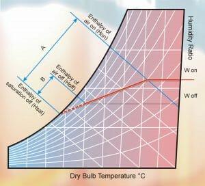
FIGURE 2
Bypass Factor
It is clear that the slope of the solid line can be varied to give different values of W off whilst keeping Hoff the same. This means that it is possible to have the same total cooling duty with different amounts of dehumidification.
A method of predicting the slope of the cooling line has been developed which uses the theory of ‘bypass factors’. The idea of this assumes that some of the air passes through the evaporator coil without coming into contact with any cold surface, and consequently is unaffected. The remainder of the air is assumed to be cooled to some point on the saturation curve. Mixing these two air streams gives the actual air leaving condition. The proportion of the total air stream, which bypasses the coil, is the ‘bypass factor’, and is represented by B divided by A.
Bypass factors (BPF) have been established for various fins, which can be used in predicting coil cooling performances. Knowing the heat transfer performance of a particular coil design, together with the air and refrigerant temperatures, it is possible to calculate a value for Hoff. The position of H sat can be found by trying different values until (Hoff-H sat)/(Hon-H sat) = BPF.
The following graphs show typical values for bypass factors. The first shows the effect of varying the fin spacing on a coil with a fixed number of rows of tubes. As would be expected, higher bypass factors and hence more dehumidification will result from wider fin spacing. In practice, with a fixed air velocity and number of rows of tubes, the only way to maintain the total cooling capacity of the evaporator would be to reduce the evaporating temperature. This is why more moisture would be removed.
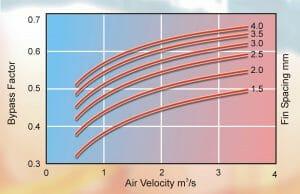
FIGURE 3
The second graph shows the effect of the number of rows of tubes in the coil on the bypass factor, whilst keeping the fin spacing constant. It will be no surprise to see less ‘bypass’ air with increasing coil depth and rows of tubes. Again, however, if everything else is fixed, fewer rows of tubes will require lower evaporating temperatures to achieve the same cooling duty.
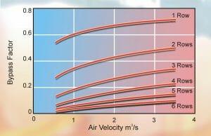
FIGURE 4
Tube Size
The rate of heat transfer from the inside tube surface to the boiling refrigerant (hi) increases with refrigerant velocity, as with air to fins. Again there has to be a balance between high values of (hi) and system penalties associated with high evaporator pressure drops. Unnecessary pressure losses through the evaporator result in lower suction pressures at the compressor and reduced compressor performance. Conversely, too low a pressure drop in a multi-stream coil can lead to poor refrigerant distribution.
In order to maintain an acceptable balance, the majority of evaporator coils are multi-streamed. That is, the refrigerant flows through a number of separate but parallel paths, or streams, from the inlet to the outlet of the coil. At the inlet, the refrigerant is distributed between the various streams, using a distributor as discussed earlier. Although some evaporator coils have large numbers of streams in order to limit the pressure drop, ultimately a change in coil tube diameter becomes necessary. Common tube diameters include 3/8″, 1/2″, 5/8″ and 3/4″. In some small domestic size air conditioners, even smaller tubes are now being used. As a general rule, larger diameter tubes will be spaced further apart, both vertically and between rows.
Coil Streaming
For optimum performance, evaporator coil streams are arranged to rise from inlet to outlet. This is to allow the vapour to flow upwards through the boiling liquid, rather than being forced downwards against its natural buoyancy.
Pressure drop through the coil causes the evaporating temperature to fall from inlet to outlet. To take advantage of this, by maximising the effective temperature difference between the air and refrigerant, a parallel flow arrangement is used where the number of rows of tubes makes this possible. The final one or two tubes in each stream, however, are arranged on the warmer, air-on, side of the coil, in order to superheat the outlet gas with the most efficient use of coil surface.
Multiple Refrigerant Sections
For standby or capacity control purposes, evaporator coils may be split into a number of refrigerant sections. Each of these has its own distributor and suction header, and is part of a separate refrigerant circuit including a compressor.
Multiple coil sections are normally interlaced, so that the air is cooled uniformly when one or more sections is not operating.
To increase dehumidification, evaporator sections may be arranged one above the other in the face height of the coil. This is achieved by satisfying the total cooling requirement with just a part of the coil, which operates at a lower than normal evaporating temperature.
Cooling capacity reduces dramatically from the air-on, to the air-off, face of the coil. It is never good practice; therefore, to have multiple refrigerant sections arranged one behind the other in series, as this produces unbalanced loading of, and the potential to overload the compressors.
NEXT MONTH: Vol 15. Plate Heat Exchangers
