 Cassette Split Systems
 Safety Gloves
 UV Leak Detection
 Condensate Drain Pipe
 Nitrogen Regulators
 Filter Driers
 Filter Cores for Core Shells
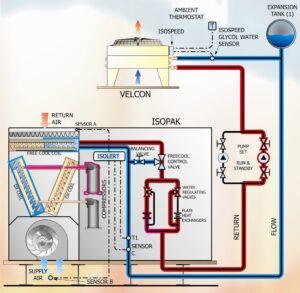
If the Return Air Temperature increases above the setpoint temperature whilst Free Cooling is fully operative, it is apparent that more cooling capacity is required. Under these circumstances, a proportion of the Free Cooling is achieved and the first stage of Mechanical DX Cooling is implemented. There can be a number of stages of Mechanical DX Cooling in a system.
In diagram 2a, when a Stage of Mechanical DX Cooling is implemented, the appropriate Head Pressure Control Water Regulating Valve (WRV) is activated to pass a proportion of the water-glycol fluid through one of the Plate Heat Exchangers (PHE). The function of the Plate Heat Exchanger is to bring into heat transfer the relatively cool return water-glycol fluid coming from the Free Cooling Coil, with the hot discharge Refrigerant of the active Mechanical DX Cooling circuit, in order to provide condensation and sub-cooling. This results in an improved COP for the Mechanical DX Cooling system.
Direct Mechanical Cooling
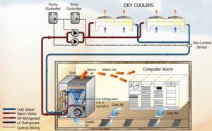
When the external ambient temperature rises to a level where Free Cooling is no longer possible, the system operates as a conventional glycol cooled air conditioning unit using the mechanical cooling refrigeration circuits to provide the full cooling capacity.
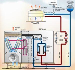
This Diagram shows the system running in Summer Operation. In this mode of operation the Free Cooling system is completely shut down, this being activated by the free cooling Bypass Valve (BV). The cooling load is now exclusively handled by the Mechanical DX Cooling, this being available in a number of stages, these being switched to match the instantaneous load. The appropriate compressor head pressure control Water Regulating Valves (WRV’s) are activated to pass return water-glycol fluid through one or more of the Plate Heat Exchangers (PHE) to effect DX condensation and sub-cooling.
Fresh Air with Supplementary DX Cooling
This close control system approach, designed specifically for Telephone Exchanges and communications apparatus rooms, uses fresh air for Free Cooling instead of water-glycol as previously described, this being combined with Mechanical DX Cooling as above.
There are three modes of operation:
- Full Fresh Air injection to the conditioned area via the air conditioning unit.
- Partial Free Cooling via Fresh Air Injection coupled with mixed re-circulated air.
- Full Mechanical DX Cooling.
Full Fresh Air injection to the conditioned area via the air conditioning unit
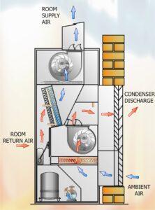
A damper system incorporated into the air conditioning unit moves to a modulated position to allow the injection of fresh air to the conditioned area. Fresh air is the primary source of cooling with this system allowing some degree of Free Cooling throughout most of the year. It is essential for the fresh air to be fully filtered to a high efficiency, this being application specific, to protect the conditioned area and any equipment within.
Partial Free Cooling via Fresh Air Injection coupled with room re-circulated air.
A damper system incorporated into the air conditioning unit regulates the room air temperature of the conditioned area by modulating and mixing warm room return air with cooler ambient fresh air drawn in from outside. Fresh air is the primary source of cooling with this system allowing Free Cooling throughout most of the year. In periods of warm weather, when the outside temperature is high the system automatically shuts off the damper and starts up the Mechanical DX Cooling compressors to provide all cooling via the DX coil.
Full Mechanical DX Cooling
In this mode, the damper is inhibited to provide Full Recirculation operation. Free Cooling via fresh air damper is not active in this mode. A number of stages of Mechanical DX Cooling are used to maintain the room air temperature in accordance with the Return Air Sensor / Room Mounted Sensor and the Controller Setpoint.
NOTE: Our sincere thanks go to Mike Creamer of Business Edge Ltd for this article.
DISCLAIMER: Whilst every effort is made to ensure absolute accuracy, Business Edge Ltd. will not accept any responsibility or liability for direct or indirect losses arising from the use of the data contained in this series of articles.
