 Cassette Split Systems
 Safety Gloves
 UV Leak Detection
 Condensate Drain Pipe
 Nitrogen Regulators
 Filter Driers
 Filter Cores for Core Shells
Vol 13 – Expansion Valve Hunting
Author Mike Creamer, Business Edge Ltd
AIR CONDITIONING TECHNOLOGY
PART 13 – EXPANSION VALVE HUNTING
Hunting describes a situation where a cyclic action of the expansion valve causes the evaporator to be overfed and underfed with liquid refrigerant. This results in a cyclic swing of refrigerant pressure and saturation temperature within the evaporator which in turn causes the average refrigerating capacity of the system to be severely reduced due to a generally lower suction pressure at the inlet to the compressor. Under extreme conditions, excess liquid refrigerant supply to the evaporator may lead to liquid flooding of the compressor with subsequent compressor failure.
Hunting is caused by a number of possibilities:
1 High refrigerant velocity within the evaporator due to undersized tubes for the application cause the liquid refrigerant to pass through the coil in slugs which can pass through the evaporator into the suction line. The expansion valve bulb experience a sudden drop in temperature as this liquid evaporates at a temperature well below the normal superheat value and causes the valve to quickly err toward the closed position. The reduced refrigerant flow that then occur causes superheat to rise considerably, which then forces the valve to open widely with a sudden increase in refrigerant flow.
2 A time lag occurs between the change of valve position and the effect at the evaporator outlet (suction line) since the revised refrigerant flow rate will take some time to travel through the tubes of the evaporator coil before reaching the outlet where the bulb of the expansion valve can sense the new condition. There will also be a time lag between a change in temperature of the outer surface of the suction line and the change in the expansion valve overall bulb temperature leading to the increase/decrease in pressure within the bulb and the action upon the diaphragm within the valve.
The time lag brought about by the combination of the above will lead to undershooting and overshooting of the desired condition with similar results on system efficiency as described in 1 above. A solution to this problem is to increase the mass, and thus the thermal response, of the sensor bulb, which will damp the rate of temperature change and the valve’s ability to respond. This will either reduce or eliminate hunting altogether.
thermal damping can be applied to air conditioning and refrigeration electronic control systems where outdoor fan speed must be varied to maintain a specified liquid line temperature at the outlet of condenser coils for Low Ambient Control, particularly as the response rate of the electronic control system is virtually instantaneous, yet the effects of fan speed changes are considerably time lagged through the condenser coil and at the liquid line. The control software can also be written in a way that overcomes this problem.
3 Over-sizing of the expansion valve will also cause hunting since an excess amount of liquid refrigerant passing through the valve will cause sudden chilling of the bulb at the evaporator outlet, thus leading to sudden temperature drop at the bulb causing a rapid closing action at the valve. The much reduced refrigerant liquid supply, after time lag, causes excessive superheat, which eventually causes the valve to open, thereby supplying to much refrigerant due to excess over-sizing. Ensure that the valve is selected for the actual capacity rating rather than a nominal capacity value.
4 Incorrect sensor bulb positioning can also lead to expansion valve hunting. If the bulb is located on a vertical outlet header connecting two or more evaporator coils, liquid may overflow a coil from above thereby chilling the bulb. The bulb should always be located on the horizontal outlet pipe from the coil to ensure this situation cannot arise as illustrated in Figure 1. Locate the bulb as close to the evaporator outlet as possible. The bulb must not be located on the underside of the suction line. The manufacturers recommendations must be followed and these may specify the 3 or 9 o’clock position or 45 degrees between the side and underside of the suction line. Insulate the bulb/suction line with high quality insulation that is impervious to water vapour, particularly on low temperature systems where the presence of moisture will lead to freezing and incorrect bulb response.

FIGURE 1
A cross-charged sensor bulb will also reduce the effects of hunting (see last months article for details of cross-charged expansion valves).
Charge Migration
The refrigerant liquid passing through the expansion valve experiences a dramatic drop in pressure and flash gas is produced as part of the liquid evaporates. This causes the body of the valve to be continually chilled. Heat is conducted from the diaphragm assembly above the valve body leading to a drop in temperature of the refrigerant charge within the diaphragm housing. Under certain circumstances, this housing can fall to a temperature that is lower that the temperature at the sensor bulb. If this situation arises with a gas charged valve, the majority of the charge will condense within the diaphragm and control of the valve will then be transferred to this point rather than at the bulb. These conditions will give rise to severe restriction of refrigerant flow to the evaporator coil and may also lead to complete shutting of the valve since the very low and almost equal temperature / pressure on both sides of the diaphragm will allow the spring to close the valve.
Gas charged valves should therefore only be used where there is a reasonable pressure drop between the valve outlet and the suction line leaving the coil. The presence of a distributor will ensure this is the case as will a coil of high pressure drop. Under these conditions, the valve body will be at a higher temperature than the bulb because the higher pressure at the valve will bring about a higher saturation temperature than that at the coil outlet by the bulb. Any migration will be toward the bulb, which will thereby retain control over the valve.
DISTRIBUTORS
The purpose of a refrigerant distributor is to provide an equal supply of liquid / saturated vapour refrigerant to a number outlets which in turn feed a multi-circuit evaporator coil. The preferred mounting position is vertical with refrigerant flowing downward to ensure gravity does not influence distribution thereby causing uneven flow although it is accepted that this effect will be minimal.
There are various type of distributor including venturi, centrifugal, pressure drop and manifold arrangements. All perform the same function.
It is advisable to use an externally equalised thermostatic expansion valve when a distributor is employed to compensate for the overall pressure drop through the distributor and evaporator coil.
FLOODED EVAPORATORS
A flooded evaporator is continually full of liquid refrigerant which leads to greater performance and efficiency as opposed to dry evaporator types where a mixture of saturated liquid, considerable saturated vapour and partial superheated vapour exist. The high liquid content leads to greater heat transfer to the body of liquid refrigerant from the air passing over the coil. Flooded evaporators are normally restricted to larger air conditioning and refrigeration systems.
Some form of control is required to maintain the evaporator full of liquid refrigerant and a reservoir (accumulator) adjacent to the evaporator is also required to provide a store of liquid refrigerant. The control normally takes the form of a float valve and this can be positioned at the inlet to the reservoir (high side) or in the evaporator or within the accumulator itself (low side). A liquid pump is employed to continually recirculate the liquid refrigerant from the accumulator to the evaporator. Excess liquid refrigerant is returned to the accumulator.
LOW PRESSURE FLOAT CONTROL
A simple float control consisting of a spherical or cylindrical chamber on a pivoting lever mechanism controls the flow of refrigerant. Some float controls modulate the flow of refrigerant to maintain the required liquid level whereas others consist of high an low level settings and open or close fully as required. As the thermal load increases, more liquid refrigerant is vaporised and the float acts to restore the liquid level to the original setting. It is
important to note that this type of control does not respond to any changes in evaporating pressure / saturation temperature within the evaporator.
A separate chamber can be positioned adjacent to the evaporator to house the float valve. One float valve can be used to maintain the desired refrigerant liquid level in two or more evaporators.
By-pass valves should be installed to allow refrigerant to flow around the float valve in the event this jams in the closed position to at least allow refrigeration to continue until the problem is rectified. A hand-operated expansion valve can be installed to allow control of the refrigerant liquid flow in the event of recirculating pump failure.
A schematic arrangement of a Low Pressure Float Control system is illustrated in Figure 2.
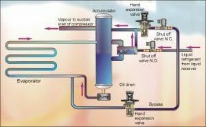
FIGURE 2
HIGH PRESSURE FLOAT CONTROL
Whilst the concept is similar to that of the Low Pressure Float Control, there are fundamental differences to this method. Refrigerant liquid from the condenser flows to the float chamber under high pressure. The float valve located in this chamber opens as the liquid level rises thereby allow refrigerant to flow to the evaporator via a pressure reducing valve. As the thermal load increases, more refrigerant vapour is produces and flows via the compressor to the condenser. The increased flow from the condenser causes more refrigerant to enter the float chamber. Clearly, the flow of refrigerant into the evaporator is directly related to the flow of refrigerant leaving the condenser and is not governed by variations in evaporator pressure / saturation temperature.
A schematic arrangement of a High Pressure Float Control system is illustrated in Figure 3.
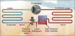
FIGURE 3
The float valve will always ensure that a limited and fixed amount of refrigerant remains in the high side condenser and the most of the liquid is retained in the evaporator as desired. However, if the refrigerant charge is too high, excess liquid refrigerant will flow uncontrollably to the compressor resulting in minor damage or serious failure. Undercharging of such a system will cause inadequate liquid supply to the evaporator and hunting of the float control. Excessive running hours will occur as the system attempts to maintain the required design temperature.
When the compressor is stopped, the liquid level in the float chamber falls causing the float valve to close thus ceasing supply to the evaporator. When the compressor starts, this liquid level rises in the float chamber, the float valve opens and refrigerant flow through the evaporator recommences.
NEXT MONTH: Vol 14 – Evaporators
