 Cassette Split Systems
 Safety Gloves
 UV Leak Detection
 Condensate Drain Pipe
 Nitrogen Regulators
 Filter Driers
 Filter Cores for Core Shells
Vol 15 – Brazed Plate Heat Exchanger (BPHE) as an evaporator
Author Mike Creamer, Business Edge Ltd
AIR CONDITIONING TECHNOLOGY
PART 15
In Vol.14 we studied fin & tube evaporators. A study of the increasingly popular Brazed Plate Heat Exchanger (BPHE) as an evaporator now follows. It is interesting to note that BPHE’s are also extensively applied as condensers in order to reject heat energy from refrigerant to water, particularly in reverse cycle heat pump applications.
Construction
The BPHE is a variant of the Gasketed Plate Heat Exchanger and is composed of a number of herringbone corrugated plates, assembled to form a plate pack.
The angle and depth of the corrugations determine the thermal transfer and hydraulic properties of the BHPE. The corrugation angles are set in opposite directions in relation to each facing adjacent plate and the plate pack is supported by the contact points formed where the ridges of the corrugations meet. The edges of each plate are folded to provide a lip which makes contact and a seal with the adjacent plate.
The plates are manufactured in an hydraulic press from stainless steel with a thin film of copper on one side. The plates are assembled to form the plate pack and this is then clamped between two end plates (not corrugated), where the inlet / outlet nozzles are attached.
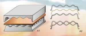
Figure 1
Brazing
In order to prevent leakage between refrigerant and water circuits, it is essential to provide an impermeable seal between the plates. This is achieved by heating the BPHE assembly in a vacuum oven to a temperature that causes the copper film to melt. As a result of surface tension, the copper coating collects at the edges of each plate and the contact points thus forming sealed channels when the assembly is allowed to cool.
Figure 2
Channel Arrangements
A channel formed by two plates with an acute corrugation angle and a relatively large channel height will have a low pressure drop and a low heat transfer coefficient for a given flow rate.
If the corrugation angle is increased and / or the channel height is decreased, the pressure drop and heat transfer coefficient are increased.
Increasing the length of the plate has a similar effect to decreasing the channel height and / or increasing the angle. Pressure drop increase due to greater flow length. Heat transfer coefficient also increases due to greater surface area, not higher heat transfer coefficient.
A plate with an acute angle is of the L (Low) type. A plate with an obtuse angle is of the H (High) type. A channel formed by n L-Plate and an H-Plate is of the Medium type. (An M-Plate does not exist). The arrangement of plates / channels is determined in accordance with the thermal performance required.
Cooling (or heating) duties with high mass flow and low heat transfer (low specific heat or a small temperature change) require L-channels. Air at ambient pressure is a good example of this situation and requires L-channels that are so extreme it is impractical to use a BPHE.
Duties with a small mass flow but with high heat transfer (high specific heat, latent phase change or large temperature change) are best achieved with H-channels. An excellent example here is the latent phase change associated with refrigerants where almost all air conditioning and refrigeration applications require H-channels.
It is also possible to mix M & H channels by constructing the BHPE with several M-channels followed by several H-channels thus producing a thermal performance between M & H channels and this is commonly applied to match the BPHE with the required performance. However, in latent phase change applications, this mixing of channel types leads to severe maldistribution of the media between the first H-channel and the last M-channel and is therefore not used in air conditioning and refrigeration applications.
A refrigeration BPHE always has all the refrigerant channels surrounded by water channels and this is achieved by having one more water channel than the number of refrigerant channels. This results in the outermost channels being water channels and the number of channel plates is also even. (This is a way of identifying a BHPE for refrigeration applications). Figure 3 shows the arrangement of plates and how the fluid flow is achieved.

Figure 3 – Plate & Channel Configuration
The construction of the BPHE and the detail of inlet/outlet porthole connections is clearly shown in the cross-sectional illustration in Figure 4.


Figure 4 and 5 (Photo) – Cross-sectional view of BPHE and Inlet/Outlet Connection
Internal Volume
The volume of the refrigerant circuit of a BHPE is approximately 2 litres for every m2of heating/cooling area. This is around ten times lower than a multi-tubular heat exchanger thus resulting in a lower filling volume and overall refrigerant charge coupled with a rapid response time to thermal load variations.
Pressure & Temperature Limitations
BPHE’s can typically tolerate a temperature range of -160 Deg C to +150 Deg C. Pressures are usually limited to 30 bar (440 psig). The burst pressure of a BPHE should be as high as 150 bar (2200 psig) since many pressure vessel safety codes call for five times the maximum working pressure (now to be termed Maximum Allowable Pressure under BS.4434) where the pressure resistance cannot be theoretically calculated.
Thermal Efficiency
The turbulence induced by the arrangement of channels and fluid flow coupled with small hydraulic diameter in a BPHE results in very high heat transfer coefficients, typically 300 – 400% greater than that attained with tubular heat exchangers. The flow of two mediums through a BPHE is virtually a true counter-current flow and this leads to a temperature difference in practice that is very close to the theoretical ideal. This counter-current flow also means that high heat recovery is possible and levels of 90% are easily attainable compared to less than 50% in a tubular heat exchanger.
Refrigerant Side Fouling in BPHE’s
Fouling on the refrigerant side of a BHPE should not normally occur other than in the form of lubricating oil presence. However, when this does occur, the consequences for the compressor and expansion valve can be severe.
The refrigerant will carry oil either dissolved within the refrigerant or as an emulsion. Oil acts as a fouling substance and also affects the heat transfer coefficient of BHPE’s used as either an evaporator or a condenser.
Refrigerant R12 coupled with a mineral oil maintains the oil in solution thus preventing the formation of an oil film other than in a direct expansion evaporator where the refrigerant evaporates and leaves the oil as droplets within the vapour. These droplets of oil can stick to the walls of the evaporator thus forming an oil film. Fortunately the heat transfer at this section of the evaporator is small (sensible heat transfer only) and so the effect of the oil film is minimal. It is essential to maintain high refrigerant velocity at this point to ensure oil does not collect in the evaporator with subsequent erratic cooling performance.
Where oil is insoluble within the refrigerant, as with ammonia (Ammonia at all temperatures and, for example, with R22 at temperatures lower than 0 Deg C), the effect varies according to whether the BHPE is used as an evaporator or a condenser.
Condenser– Since R22 dissolves oil at normal condensing temperatures, oil does not cause any significant problem. The effect for insoluble oil will also be smaller than in the evaporator because the higher oil temperature results in lower oil viscosity and this coupled with gravitational and shear forces move the refrigerant and the oil in the same direction toward the outlet of the condenser thus preventing oil accumulation in the condenser.
Evaporator– Oil suspended within the refrigerant forms a film on the heating surface for both dry and wetted evaporation. Provided the refrigerant velocity is high enough, the oil will be carried out of the evaporator. The formation of an oil film on the wetted section of the evaporator where the majority of heat transfer occurs (latent heat of vaporisation) has a significant effect on heat exchanger performance.
Oil Decomposition Products
The high discharge temperatures created in the compressor can cause the oil leaving the compressor within the refrigerant to be heated above its decomposition temperature. This may then result in the formation of a wide range of decomposition products ranging from carbon to tar-like substances. These compounds inevitably find their way to the heat exchangers. As the evaporator is the coldest temperature region of the system, where any liquids present will have highest viscosity, it follows that the evaporator has the highest affinity for fouling.
This problem is more severe for a refrigerant that does not dissolve the lubricating oil. Refrigerants that dissolve oil have a tendency to wash away the oil along with the decomposition products. Unfortunately, these compounds will then return to the compressor to potentially cause other problems.
Wear & Tear
Solid particles produced from wear and tear of the compressor can also ultimately find their way to the heat exchangers. Interestingly, the presence of such particles within the evaporator can be slightly beneficial as these form what are known as nucleation boiling sites which increase the nucleate boiling heat transfer coefficient.
Water
The presence of water in the system when combined with the lubricating oil and oil decomposition products can form a sludge that may settle of heat exchanger surfaces, particularly in the evaporator due to the lower temperature / oil viscosity mentioned above. These substances can also cause the refrigerant to foam resulting in impaired heat transfer.
Design
Evaporator design should aim for good oil entertainment to eliminate oil logging and this is achieved by ensuring high refrigerant velocity to create high shear stress. The shear stresses are proportional to the pressure drop per unit flow length.
Liquid Side Fouling in BHPE’s
The liquid side of an evaporator normally deals with a recirculating liquid in a closed loop. This liquid is usually water or water containing a freezing point depressing solute (anti-freeze) such as ethylene glycol or methanol brine. The closed loop should ensure that the recirculating liquid remains reasonably pure and problem free.
The most common impurity is oil and greasy products. Glycol solution at higher concentrations can dissolve or at least disperse oil thereby creating a self-cleaning effect. The varying properties of the circulating liquid will determine the nature of the impurities and fouling problems generated and appropriate measures will have to be taken to limit these or a regular cleaning process will have to be employed to remove them.
Fouling can be classified as Pressure Drop, Surface Fouling and Settling of Solids.
Pressure Drop Fouling
Particles in the water including fibres and corrosive elements clog the inlet of the evaporator and / or channels and tubes. This inevitably leads to a reduction in flow and therefore thermal performance. Pressure drop increases. Small particles are likely to pass through the heat exchanger but the presence of fibres is more likely to cause partial blockages.
Surface Fouling
This occurs when the heat exchanger surface is progressively covered by a layer of fouling products. The thermal performance of the heat exchanger deteriorates but the pressure drop is only marginally affected initially The layer of fouling products can be caused by:
Sticky Products – Oil and grease enter the water circuit and stick to internal surfaces.
Scaling – Inorganic salts such as CaSO4,calcium sulphate, have an inverted solubility curve (solubility in water increases with increasing temperature). When cold water makes contact with a warm condenser surface, these salts deposit on the surface. Pure calcium sulphate is very difficult to dissolve thereby making cleaning a difficult or impossible task. Another component of the scaling, CaCO3,calcium carbonate, is easily dissolved by diluted acids.
Composition and concentration of the salts, pH and temperature are the factors that influence the scaling rate. Scaling is seldom found where heat exchanger wall temperatures are below 45 Deg C. Scaling will note therefore form in evaporators unless the application involves reverse cycle heat pump operation where temperatures in excess of 45 Deg C are almost certain to occur.
Bacteria – This can grow anywhere and cannot be trapped in a filter or strainer thereby making it impossible top prevent growth under the right conditions. Bacteria can feed on the sulphates in the water and convert these into sulphuric acid which can then lead to corrosion. Some forms of bacteria feed on iron (dissolved or oxides) forming a coat of a viscous nature. Some feed on nitrogen or phosphor compounds forming a slime on heat exchanger surfaces. Warm conditions are usually best suited to such growth and the most likely sites are the water cooled condenser or the reverse cycle evaporators. The water can appear to be perfectly innocent at certain points yet whilst containing bacteria growths at certain sites which makes this condition particularly difficult to detect.
Fungi – This creates similar effects to Bacteria but are more difficult to eliminate. The attack on heat exchanger surfaces is not too detrimental. The presence of fungi in cooling towers will however attack any wood present in the construction materials.
Particles – Particles of sand and other materials can be found in some systems and these can lead to blockage of the BPHE inlet at low water velocities.
Please note that most of the information relating to refrigerant and liquid side fouling, oil entertainment, oil decomposition and water in the system also apply to conventional fin & tube evaporators, water chiller evaporators, air cooled and water cooled condensers.
NEXT MONTH: Vol.16 – Shell & Tube Evaporators
DISCLAIMER: Whilst every effort is made to ensure absolute accuracy, Business Edge Ltd will not accept any responsibility or liability for direct or indirect losses arising from the use of the data contained in this series of articles.
