 Cassette Split Systems
 Safety Gloves
 UV Leak Detection
 Condensate Drain Pipe
 Nitrogen Regulators
 Filter Driers
 Filter Cores for Core Shells
MASTERCLASS – AIR CONDITIONING TECHNOLOGY
VOL 53 – Fan Coil Unit Selection – Noise Level
In last month’s article (VOL 52) we examined the advantages and disadvantages of airside over waterside fan coil units.
We continue this month with an overview of the selection criteria that need to be considered when selecting Fan Coil Units with particular emphasis on noise.
Fan-Coil Units
Due to design and size restrictions, Fan Coils can very often end up as a compromise and can only meet consultant / contractor requirements within a band of reasonable tolerances and base requirements.
There are two main types of Fan Coil systems. Which of these to use must be decided upon before a number of other factors can be considered. These two systems are based on either “Air Side “ or “Water Side” control. Both have advantages and disadvantages and these will be discussed later on in this text.
If we look at the overall concept of a Fan Coil and the initial requirements for their selection, from either system type, we should consider the following factors: –
- Noise Level
- Air Volume and External Static Pressure requirements
- Leaving Air dry bulb / wet bulb temperature requirements
- Cooling / Heating Requirements
- Water Flow / Return Temperature and Water Flow (cooling and heating)
- Type of control system
- Condensate removal
- The Fan Coil selection
Noise Level
This is one of the main factors requiring serious consideration and attention. A Fan Coil system may succeed or fail based upon the final noise levels attained, and this factor can often be overlooked. Other influencing factors regarding the noise levels experienced, which should be taken into consideration are, the height of the ceiling, type of ceiling construction, general room acoustics, and how the Fan Coil is secured and positioned.
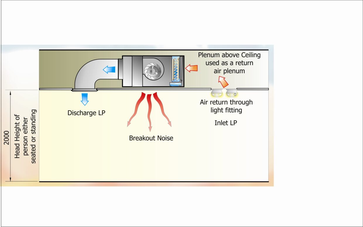
Another common reason for underlying problems is the discharge noise level, in conjunction with the inlet and case “breakout” noise being overlooked. As the area above the false ceiling is used as a common return air plenum with a duct close to the inlet of the Fan Coil, the inlet of the Fan Coil is usually open to the conditioned area without any extra attenuation. In these cases, an inlet plenum specifically designed for the Fan Coil, which enables the filter to be removed, should be fitted to the inlet, particularly in installation situations containing sensitive areas.
The quoted “NR” (Noise Rating) level is a guide for the Fan Coil Unit only and it is essential that the octave band charts are obtained. The octave bands will be used in conjunction with the type of ceiling and room acoustics to perform the necessary calculation to arrive at the overall NR for the room. The quoted NR level is usually for the discharge noise.
The inlet noise and breakout is far more important to consider than the discharge noise. The discharge noise has an attenuation effect from the ducting, and as long as there is no regenerated noise from the grilles, the actual noise levels experienced can be less than the manufactures figures. The inlet, however, is often positioned near a light fitting and there is very little in extra attenuation.
Noise Data
In the following examples, noise is dealt with utilizing “NR” which gives a guide to the expected noise level. Using a sound power or pressure spectrum as a basis, and then applying factors would achieve a more accurate result. However, this is a much more complicated process.
In the tables the noise (pressure) level (Lp) is indicated on the outlet side in relation to the air displacement and the external pressure. The noise level on the suction side is 4 NR less. These values are based upon the use of one Fan Coil in a room with a volume of 350 m3 and reverberation time of 0.5 seconds.
For rooms with different volume and/or reverberation time a correction factor must be calculated in accordance with the formulae or tables 1 to 4 inclusive.
Basic information
The noise level is based upon an installation in which the air is taken in indirectly via the plenum above a false ceiling or via an external intake duct (e.g. ventilation). The air is blown into the room itself via a 90° mitered bend and input grille. The noise levels are measured 2mtrs from the input / output grille (unrestricted field radiation, 0 = 2).
With direct intake via a grille in the ceiling, the noise level in the room is 1.5 NR higher than the table value. This correction value is based upon the noise level difference between intake and output of 4 NR.
Calculation of Noise Level
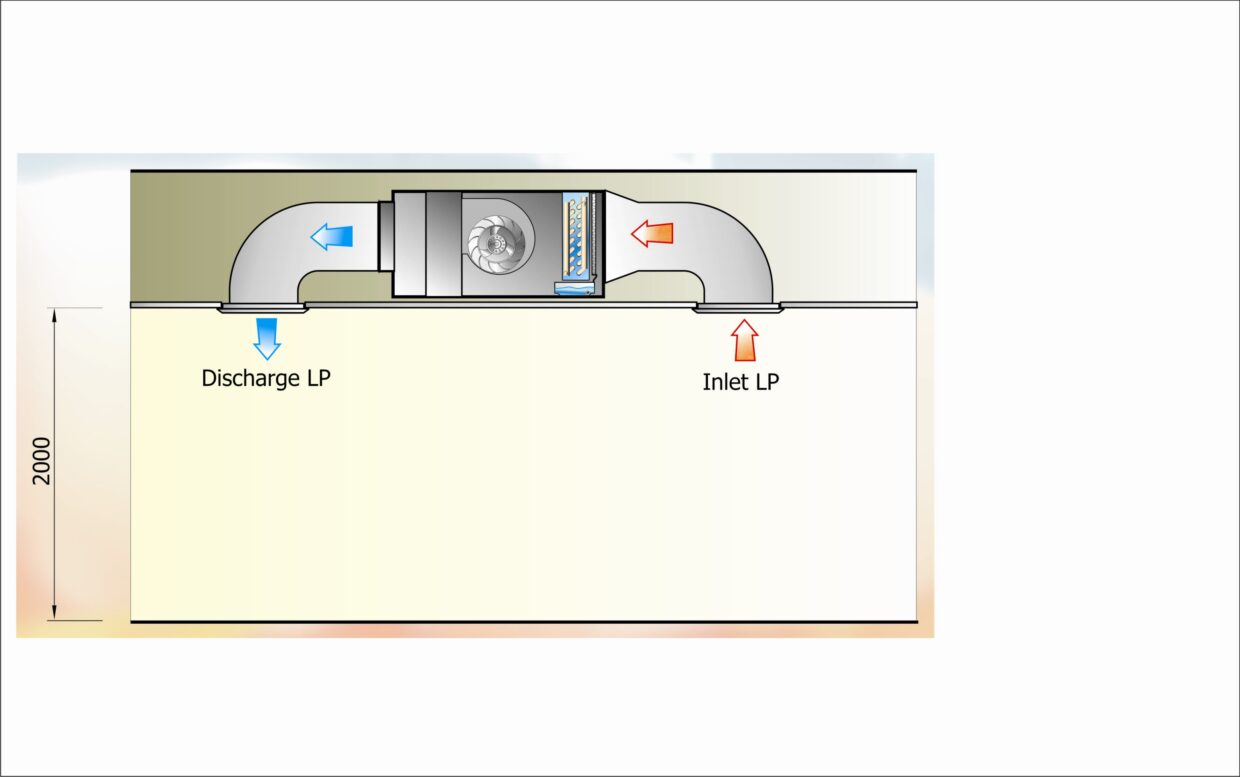
Example 1 (Fig 1)
Intake and output in same room, with no additional attenuation.
Noise Level output = 37.5 NR
Difference intake / output = 4.0 NR
Correction as per table (Table 4) = 1.5 NR
Lp (total) = 37.5 NR + 1.5 NR = 39 NR
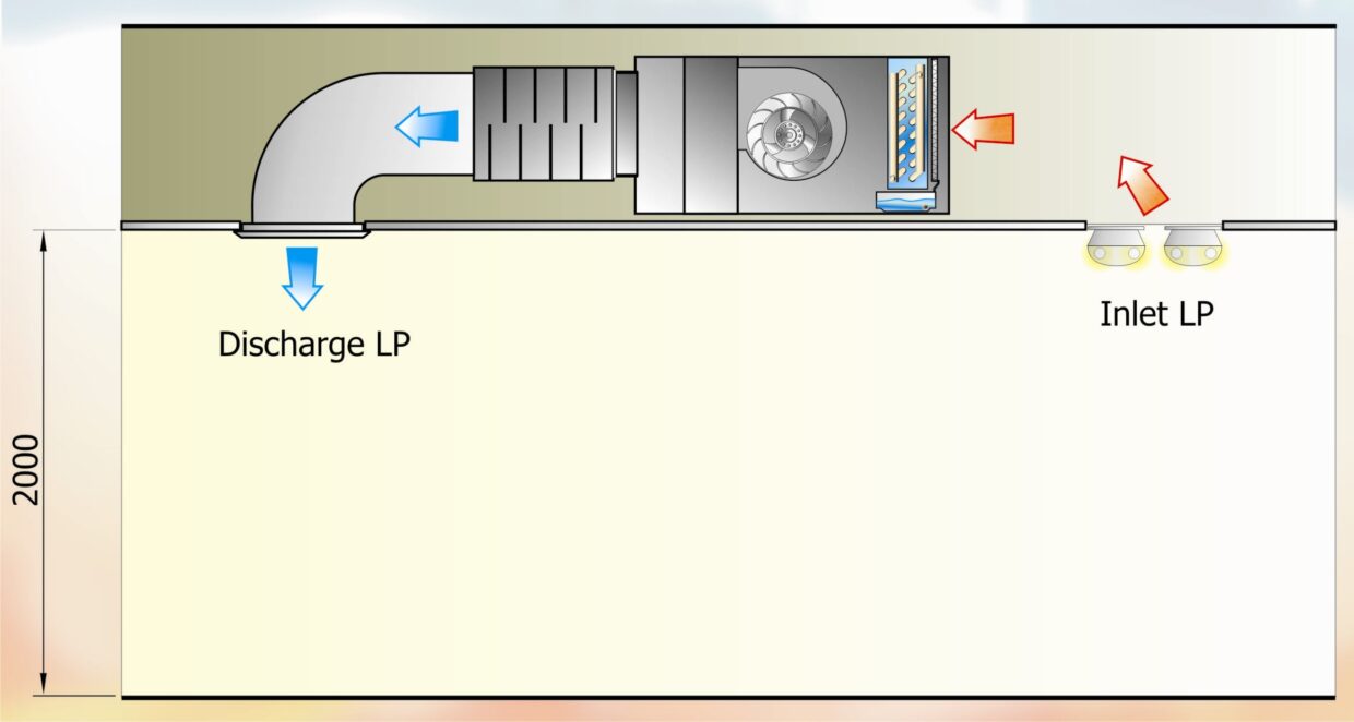
Intake via plenum above acoustic ceiling and output direct into the room, with no additional attenuation.
Noise Level output = 37.5 NR
Difference intake / output = 4.0 NR
Attenuation of acoustic ceiling = 10.0 NR
Total difference = 14.0 NR
Correction as per table (Table 4) = 0.0 NR
Lp (total) = 37.5 NR + 0.0 NR = 37.5 NR
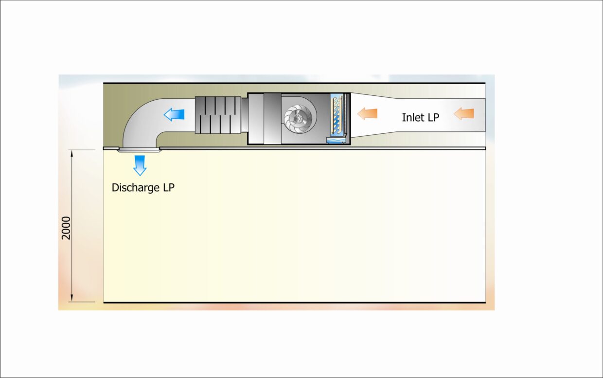
Intake from outside via an external duct and output direct into the room, with no additional attenuation. Standard ceiling not acoustic.
Noise Level output = 37.5 NR
Difference intake / output > 10.0 NR
Correction as per table (Table 4) = 0.0 NR
Lp (total) = 37.5 NR + 0.0 NR = 37.5 NR
Intake and output in same room, with additional attenuation on inlet and discharge. The attenuators give a reduction of 15 NR
Noise Level of unit output prior to attenuation = 50.0 NR
Noise Level of unit input prior to attenuation = 46.0 NR
Noise Level of unit output after attenuation = 35.0 NR
Noise Level of unit input after attenuation = 31.0 NR
Difference intake / output = 4.0 NR
Correction as per table (Table 4) = 1.5 NR
Lp (total) = 37.5 NR + 1.5 NR = 36.5 NR
See example five drawing.
Intake via plenum above acoustic ceiling and output direct into the room, with additional attenuation on discharge. The attenuator gives a reduction of 15 NR
Noise Level of unit output prior to attenuation = 50.0 NR
Noise Level of unit input prior to attenuation = 46.0 NR
Noise Level of unit output after attenuation = 35.0 NR
Noise Level of unit beneath false ceiling = 36.0 NR
Difference intake / output = 1.0 NR
Correction as per table (Table 4) = 2.5 NR
Lp (total) = 35.0 NR + 2.5 NR = 37.5 NR
Example 6
See example six drawing.
Intake from outside via external duct, and output direct into the room, with additional attenuation on discharge. The attenuators give a reduction of 15 NR
Noise Level of unit output prior to attenuation = 50.0 NR
Noise Level of unit output after attenuation = 35.0 NR
Difference intake / output > 10.0 NR
Correction as per table (Table 4) = 0.0 NR
Lp (total) = 35.0 NR + 0.0 NR = 35.0 NR
Abbreviated Correction Values for Noise Data Calculations Tables 1-4
Table 1 Other room volumes
Lp2 = Lp1 + 10 log(V2/V1)
Lp1 = noise level (from tables)
Lp2 = actual noise level for new room volume
V1 = Reference room volume (350m3)
V2 = volume of actual room
| Volume (m3) | Correction NR |
| 100 | +5.5 |
| 150 | +3.5 |
| 200 | +2.0 |
| 250 | +1.0 |
| 300 | +0.5 |
| 350 | 0 |
Table 2 Other room reverberation time
Lp2 = Lp1 + 10 log(T2/T1)
Lp1 = noise level (from tables)
Lp2 = actual noise level for new reverberation time
T1 = Reference reverberation time
T2 = Reverberation time of actual room
| Reverberation time (s) | Correction NR |
| 2.5 | +7.0 |
| 2.0 | +6.0 |
| 1.5 | +4.8 |
| 1.0 | +3.0 |
Table 3 Units with same noise level in one space
Lp2 = Lp1 + 10 logn
Lp1 = noise level (from tables)
Lp2 = actual noise level for new room volume
n = number of units
| Number of units | Correction NR |
| 2 | +3 |
| 3 | +4.8 |
Table 4 Addition of two noise sources with different values
| Difference NR | Correction NR |
| 0 | +3.0 |
| 1 | +2.5 |
| 2 | +2.1 |
| 3 | +1.8 |
| 4 | +1.5 |
| 5 | +1.2 |
| 6 | +1.0 |
| 7 | +0.8 |
| 8 | +0.6 |
| 9 | +0.5 |
| 10 | +0.4 |
| >10 | 0 |
Air Volume and External Static Pressure
Air volume, pressure drop and noise requirements should be specified first and in preference to fan speed. As noise is a function of air volume and external static pressure, these are definitive values and not as subjective as fan speed. The fan speed is a variable depending on the type and manufacture of fan impeller/motor.
The required air volume is determined by the thermal performance requirements of the Fan Coil, in both terms of heating and cooling loads. Once selected, the Fan Coil then has to meet the overall External Static Pressure requirements of the installation. This is determined by a number of factors including discharge air plenum arrangement, number of spigots, length and type of supply air ducting to the terminal, the arrangement of the ductwork in terms of bends, and characteristics of the supply air diffuser.
The amount of fresh air requirement needs to be thought about as this can have a dramatic effect on the unit. The fresh air can be treated, giving an year round temperature. Fresh air is normally taken as a percentage of the overall total volume.
Leaving Air Temperatures (dry and wet bulb)
The cooling and/or heating capacity of each Fan Coil will be stated by the supplier against the given load. However, whilst the selected Fan Coil may have sufficient capacity to meet the load, it is very important to look at the Leaving Air Temperature. It is important to ensure that the temperatures stated are indeed the actual leaving air temperatures at the Fan Coil discharge point, after allowance has been made for any casing heat gains or losses. Also ensure that the leaving air temperatures are acceptable, especially for the cooling requirement since air supplied to the conditioned space at too low a temperature will not be acceptable to the occupants.
Depending on the height of the ceiling, the temperature should not be too cold or too hot. The preferred figures can be obtained from the CIBSE guide.
Cooling & Heating requirements
There may be a requirement for a heating-only, cooling–only or combined heating/cooling system. This will determine whether Fan Coils based on a 2 pipe or 4 pipe system are required. The basis for this has already been covered in detail in preceding Masterclass articles. Where cooling is concerned, the design capacity can be specified on the basis of the “Total” cooling required, “Sensible” load or both. If both are provided, then it should be specified which is the most important for the application and this will then be subsequently used for calculations and equipment selection.
The entering air condition to the Fan Coil (air “on”) must be specified. This will be the same as the Room Design Condition where there is no fresh air introduction. Where fresh air is introduced, different mixed conditions for summer and winter will apply. The return air temperature and the primary air mix may also be specified. If the entering air condition is given as a breakdown, it is best to specify the return air volume in relation to the primary (fresh) air volume as a percentage since the Fan Coil is unlikely to exactly match the required air volumes and a compromise must therefore be reached.
Note that a different Room Design Condition (return air condition) might be specified for summer versus winter operation.
If there are any water pressure drop restrictions or limits, these should be specified prior to selection, as this will influence the size of the Fan Coil.
Water Flow Rate
The manufacturer will give the required water flow rate and pressure drop for the cooling and heating coils. The pressure drop will vary according to how the coil is circuited. This will also affect the minimum flow rates that must be observed for optimum performance. The flow rates should therefore be checked to ensure that they reflect the full coil duty, including any effects due to heat gains or losses within the unit, thereby enabling correct pipe sizing to the fan coil units.
Using the water flow rate and pressure drop data, a control valve selection can be made. To enable the valve to operate correctly, the valve selection should be made so that the valve “authority” is as near linear as possible.
Water Temperatures
These will effect the size of the unit, as well as determining how “wet” or “dry” the coil would be. The temperature of the water will directly affect the overall “off” temperature of the fan coil unit.
If the water “on” temperature is too low, then the coil will be “wet” and there will be a latent effect. If the water “on” temperature is too high, the air ”off” temperature will be too high.
The water temperature rise influences the available duty of the coils.
Type of Control System
The type of control system used will directly determine how effective the Fan Coil Units will perform. The available control system types fall into three main categories:
- Analogue
- Digital
- BMS (Building Management System)
Analogue
This is a simple and often the cheapest system of control. This type of control is usually utilised when there is only a small number of fan coil units or full control of the system is not required.
Digital
This has a finer control with a number of fan coil units being able to be “linked” enabling a “controlled” conditioned space from single or multiple temperature sensors.
BMS (Building Management System)
This is an extension to the “Digital” system; a BMS system will provide full control of the Fan Coil Units and will also provide actual inlet, output temperatures from each fan coil unit, along with the room temperature.
This is a brief overview as “Controls” is a diverse and complex subject, which will be dealt with separately in future issues.
Condensate removal
The removal of the condensate is a very important design consideration. If this element is not correctly designed and installed, serious detrimental effects on ceilings, furnishings and end user equipment such as computers can occur. It is a simple matter to calculate the volume of condensate that will be produced although in many instances, this will be ignored on the basis that the condensate pipes are simply assumed to be large enough. The manufacturer of the Fan Coil will normally provide the condensate flow rate for a given unit running under the specified design conditions within its technical literature.
The condensate flow rate coupled with reasonable distance to the nearest drain point may require the fitting of condensate pumps. The ceiling void height and the fall attainable in the drain line to the nearest drain outlet will also help determine this. Condensate pumps can be fitted within each Fan Coil Unit or a larger common pump can be installed serving three or more Fan Coil Units.
Types of fan coil units
Airside
These units have separate heating and cooling coils with a bypass duct. These cost more than the equivalent waterside unit when looked at side by side, but when valves are taken into account the overall cost is similar. The advantage is that with separated coils, and a bypass, the “off” temperature of the unit can be finely controlled, with very little time lag. The disadvantage is the “heat” / “cooling” pickup with both coils is “live”.
Waterside
This is the conventional fan coil arrangement with a combined coil block, which contains a heating and cooling coil together. Therefore the unit can heat or cool, but not both together. Therefore from cooling to heating and vice versa can have a lag in the region of several minutes. This means that the coil selection is important to ensure no cold or hot draughts. The valve selection is very important to ensure linear operation and speed of response.
Remember that a “fan coil” unit is a compromise! Here is a summary of Fan-Coil information and who should provide it
THE CONTRACTOR – information he must provide
· The Duty
· Air Volumes – Fresh Air and Total
· Air On Condition – Fresh Air and Total
· Room design condition – Noise and temperature
· “On” Water temperature
· Water Temperature rise
· Maximum Water pressure drop
· External Fan resistance
THE MANUFACTURER – information he must provide
· The basis of the selection process
· Coil data selection
-
Water flow rate
-
Air “Off” coil condition
· Fan selection
· Noise data
DISCLAIMER:
Whilst every effort is made to ensure absolute accuracy, Business Edge Ltd. will not accept any responsibility or liability for direct or indirect losses arising from the use of the data contained in this series of articles.
