 Cassette Split Systems
 Safety Gloves
 UV Leak Detection
 Condensate Drain Pipe
 Nitrogen Regulators
 Filter Driers
 Filter Cores for Core Shells
MASTERCLASS – AIR CONDITIONING TECHNOLOGY
In last month’s article we completed our study of low ambient control methods under the current category of our review of Control, Safety & Protection Devices used in the Vapour Compression Cycle. This month we will concentrate on compressor protection devices with the emphasis on the important topic of lubrication and its associated control devices for system protection.
Oil.
It is ironic that refrigeration system designers have to spend considerable time and money keeping the majority of the system free of oil and yet are obliged to introduce oil into the system in order to protect one component, the compressor.
Oil must be introduced into the compressor in order to provide lubrication for the surfaces experiencing friction, primarily the bearings, these being on the crankshaft, connecting rod bearings, both the big and small end bearings. The other rubbing surfaces are the cylinder walls where in addition to providing lubrication the oil film assists in providing a seal between the piston and cylinder wall to reduce blow back.
Lubrication of these components can be provided by splash-feed or pressure feed.
Splash-Feed, as the name implies, is caused by the action of the crank shaft rotating and dipping the cranks and the big end of the connecting rods into the oil sump and splashing oil onto the internal surfaces of the compressor. This type of lubrication is normally restricted to reciprocating compressors (Open and Semi-Hermetic) of less than 2.5kW and hermetic compressors (Reciprocating, Rotary sliding Vane, and Scroll). Compressors using this form of lubrication do not normally incorporate any form of oil failure protection, although some manufacturers can supply an oil float switch to give warning if the oil level falls below safe level. This float switch would be recommended if long pipe lines were involved or applications which were at risk due liquid refrigerant returning, such as reverse cycle defrosting. Some compressors, normally open type, feature an extension of the connection rod big end bearing in the form of a dipstick which splashes into the oil bath in the sump.
A splash rotor can also be fitted at the rear end of the crankshaft in the form of two arms which splash lubricant from the sump to the roof of the compressor body where it then falls into a gallery at the end of the crankshaft for subsequent distribution along drillings in the crankshaft and channels in the journals. The oil is then allowed to flow freely through drillings in the connecting rod big ends back to the sump. Such compressors can be run for prolonged periods at very low speed (200 rpm) making them especially suited to transport refrigeration applications.
Larger compressors use pressurised oil which is pumped to the various bearings and surfaces from a mechanical oil pump via small channels which have been drilled into the crankshaft, connecting rods and the compressor body. These oil pumps are in most cases fitted as an integral part of the compressor and are directly driven by the crankshaft.
Larger compressors such as screw and centrifugal machines use an oil pump in the form of a totally separate item driven by its own motor. The oil management systems of certain large water chillers and other systems can be very complex.
Failure of the oil pump in any type of compressor (other than oil-less type) will usually result in catastrophic damage to the compressor if such failure is not detected quickly enough.
There are a number of components available to protect against oil failure but they all must in one way or the other be able to measure the crankcase pressure and the oil net pressure. Possibly the most common is the Oil Differential Pressure Switch.
The object of a pressure differential switch is to measure or compare the differences in pressure being exerted within a system. The pressures in this case are the refrigerant pressure within the crankcase and the pressure generated by the oil pump.
All the oil circulated by the oil pump eventually returns to the crankcase sump. In order to enter the sump, the oil pressure has to be greater than the crankcase pressure, therefore the effective oil pressure or net oil pressure is, the total pressure generated by the oil pump minus the crankcase pressure
The essential requirements of a differential oil pressure control fitted to a compressor with an oil pump are ;
- To be able to subtract the crankcase pressure from the oil pressure and to measure this difference.
- Since at start-up there will not be a pressure difference between oil and crankcase, a timer must short out (By-pass) the safety pressure switch for a predetermined time to enable the compressor to start and generate an oil pressure. If insufficient pressure is provided by the oil pump after the allotted time, the pressure switch must switch the compressor off.
- Ideally the oil safety switch will incorporate a warning light to show that it has tripped and a “normal” light to show correct operation.
- If the oil switch should trip-out due to insufficient oil pressure, it should not be able to reset itself automatically and therefore, a Manual Reset button must be incorporated.
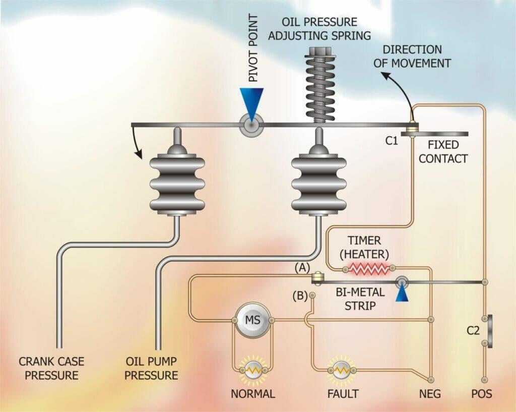
Figure 1 shows how the above functions are achieved. The oil switch control has two pressure sensing bellows, one connected to a tapping on the compressor crankcase to measure vapour pressure, and the other bellows is connected to a tapping on the oil pump which is subject to the oil discharge pressure.
These two bellows are in equilibrium when the compressor is at rest and all internal pressures have equalised. The contacts C1 and (A) will be closed. When the compressor is required to run contact C2 closes.
When contact C2 closes, current flows through contact (C1) to the heater and (A) to the motor contactor solenoid Ms. The “Normal” indicator lamp will illuminate and the compressor will run. If the compressor oil pump works correctly, the pressure in the oil side bellows will build up, exceeding the pressure in the crankcase bellows plus the pressure exerted by the oil pressure adjusting spring, and contact C1 will open, de-energising the timer heater.
If the oil pressure fails to reach the required pressure, contact C1 remains closed and the heater continues to heat the bi-metal strip which has been selected to bend after 120 seconds (in some cases 90 seconds) at which point the bi-metal strip bends and breaks contact (A) and makes contact (B).
The compressor will stop, the “Normal” lamp will go out and the “Fault” lamp will illuminate.
In order to reset the switch, the Manual Reset button would force the bi-metal contact back to (A).
If during the run cycle oil pressure should fall, then contact C1 will re-make and the heater will be energised. After the predetermined time, 120 or 90 seconds, the bi-metal strip will open contact (A) unless, of course, oil pressure is re-instated within this time. This method of control protects against transient faults which may temporarily reduce oil pressure.
When fitting an Oil Differential Pressure Switch, ensure that the switch is located above the oil level of the compressor since this prevents oil migrating into the vapour bellows and interfering with the operation of the switch.
As in all methods of control, electronic control can replace the common electro-mechanical controller and extend the range of protection given to a compressor. Electronic controllers can measure the viscosity of the oil being fed to the compressor and if the oil contains excessive quantities of refrigerant, the compressor can be switched off. These controllers can:
- Keep a record of the number of times the Oil Differential Pressure Switch fails to reach pre-determined set points
- Measure oil temperature and either warn or switch off the compressor if the oil temperature is too high
- Measure the pressure drop across the oil pump filter and give warning when this pressure drop starts to rise.
A good general rule is: The larger your compressor or the more critical your application, the greater the sophistication of your compressor protection.
DISCLAIMER: Whilst every effort is made to ensure absolute accuracy, Business Edge Ltd. will not accept any responsibility or liability for direct or indirect losses arising from the use of the data contained in this series of articles.
