 Cassette Split Systems
 Safety Gloves
 UV Leak Detection
 Condensate Drain Pipe
 Nitrogen Regulators
 Filter Driers
 Filter Cores for Core Shells
MASTERCLASS – AIR CONDITIONING TECHNOLOGY
VOL 43 – Textile Based Air Distribution Pt1
In last month’s article (VOL 42) we completed a 3 Part study of Air Handling technology and the relevant Air Handling Equipment.
This month we commence the next module dedicated to form of air distribution technology that is steadily gaining increasing acceptance throughout the Refrigeration and HEVAC industries.
Textile Based Air Distribution
Textile Ducting, or “Air Socks” as they are more affectionately known, has been around for more years than people would believe and yet still it is new to many people in the AC&R and HEVAC industries. One early record of textile ducting being used is in 1955 for a cotton mill in Germany. People that are aware of the product normally only associate it with the Food Industry and sometimes the Textile Industry. Although they are two classic applications it is very far from the truth. By the means of strategically positioned nozzles or holes in specially selected materials, for which the combinations and permutations are endless, virtually the whole spectrum of air distribution requirements can be ardently satisfied for Heating, Cooling and Ventilation with remarkable results.
Textile ducting has the ability to optimise uniform air distribution throughout the room and so achieving a quality homogeneous environment. The system is able to achieve this by virtue of the fact that the entire length of the duct is used for discharging the supply air into the conditioned space, this being impractical or very expensive for many conventional rigid duct systems.
The exception to this is where the textile duct maybe used for displacement ventilation. Here, smaller air volumes can be used with larger temperature differentials dropping the supply air into the occupied zone away from room occupants and then push the warm air to the extract grilles. Displacement ventilation being very efficient for applications where there are particularly high heat loads such as in TV studios, Computer Suites or Printing Shops. In such applications, by the very nature of the principles, the temperature across the area will have a wider band of temperatures and typically there will be a blanket of warm air just below the ceiling; the ceiling being where the extract grilles are normally to be positioned.
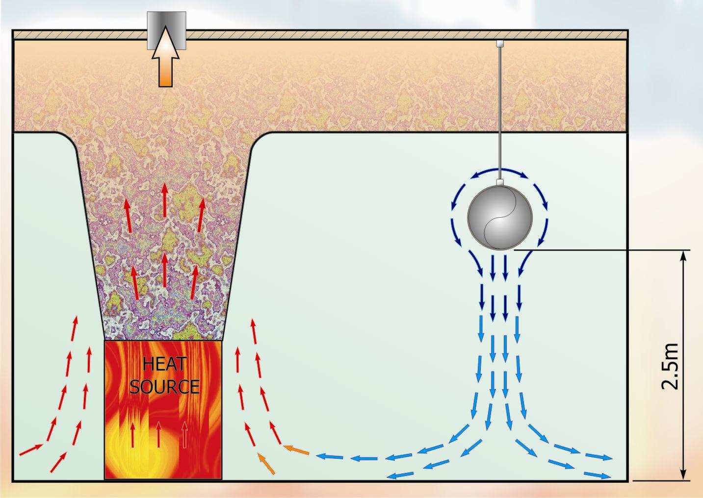
Fig 1
Figure 1 – Low Impulse Textile duct supplying cooling air to displace heat gain from large heat source(s)
|
Typical Applications |
||
| Swimming Pool Halls | Restaurants | TV Studios |
| Sports Centre Halls | Theatres | Industrial Manufacturing |
| Fume Cupboard Labs | Gymnasiums | Cheese Ripening Rooms |
| Electronic Manufacturing | Retail Outlet Units | Cigarette Manufacturing |
| Warehouses | Chilled Food Prep Areas | Cheese Storage Rooms |
| Commercial Kitchens | Bakeries | Shops |
| Pharmaceutical Production | Printing Factories | Public Areas |
| School Classrooms | Meat Carcass Batch Cooling. | Close Control Rooms |
| Offices | Textile Weaving Mills | Computer Suites |
Features
- Various Principles of Air Distribution ~ Mixing, Induction, Displacement, Draught-free, and Spot Cooling.
- Quiet in operation, the system makes no noise and the material provides some attenuation hence it is used for recording studios.
- Permeable textile ducting is free of Condensation and doesn’t require insulation.
- Economical installation costs ~ 2 to 3 times quicker than conventional systems.
- Hygienic system ~ the textile ducts can be easily removed for laundering when required.
- Draught-free and even air distribution providing a virtually homogenous environment with no dead zones.
- Low weight for suspension considerations, weight of material approx. 300g/m2 and suspension system approx. 550g/m.
- Standard and special colours to suit the ambience of the environment.
- Architecturally interesting with aesthetics designs.
- Different types of material are available.
- Materials are all man-made synthetic materials and therefore don’t support the growth of micro-organisms ~ hence approved for use in the Food Industry.
- Minimal weight and size for transportation considerations.
- Different Shapes ~ “O” Circular, “D” Semi-circular and Quadrant are the most popular.
- Textile and Fabric ducting systems can be fitted to existing heating and air conditioning systems.
- Textile Ducting is now extensively available in Flame Retardant ®TREVIRA CS.
Types of Ducting
In the main there are two types: The first being “Low Impulse” and the second “High Impulse”. The former type is a permeable woven textile through which the air diffuses at a very low velocity, typically 0.07-0.11 m/sec. The “High Impulse” type takes the form of a non-permeable material into which 5 mm diameter holes are strategically punched in specifically designed patterns, these hole patterns are critical in achieving the required air distribution and the correct level of comfort specified for the occupied zone.
Design Considerations
Although, the air is discharged through the textile duct surface at very low velocity this property alone is not enough to guarantee a draught free environment. Similarly, for high impulse type of ductwork, careful calculations are needed to ensure that the air velocity is in accordance with the comfort required. These calculations refer to the throw, penetration, relative air density, hole pattern, duct static pressure, and the orientation of holes. It is for this reason that an assessment for the area must be made, these items are:
- Cooling/heating Watts per metre length of textile duct.
- Cooling/heating Watts per square metre of floor area.
- Air volume per metre length duct.
- Room temperature.
- Supply air temperature.
- Positioning of the ducts.
- Required room conditions.
- Activity of room occupants.
- Clothing of room occupants.
- Purpose of the room.
- Objectives of the cooling/heating capacity.
With this information, reference should then be made to the information contained in Table A in order to determine the room category. If this design procedure is not followed then the project will inevitably comprise either too little ducting or too much ducting, neither of which is desirable and most probably the quality of the room environment will suffer.
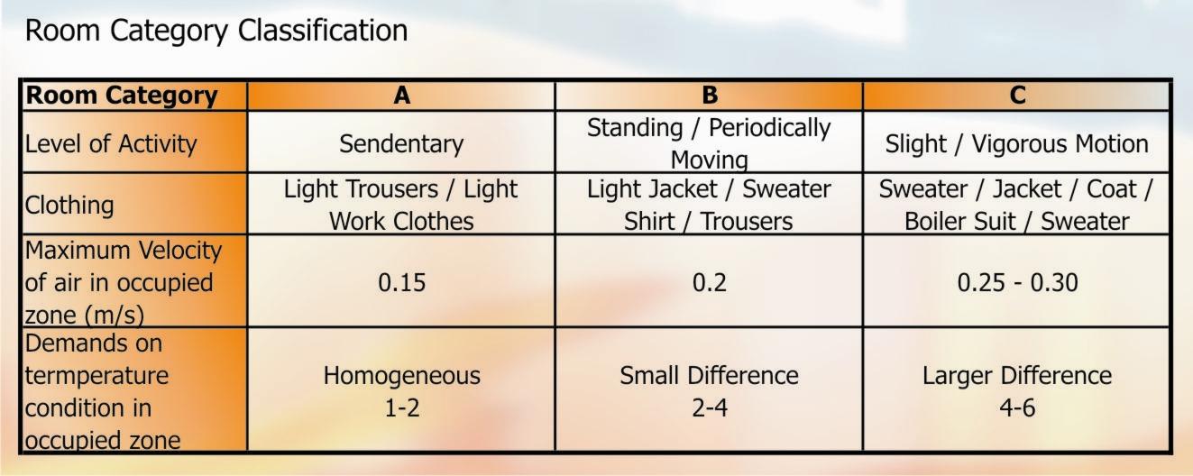
Table A – Room Category Classification.
Low Impulse
This system has the ability to handle large volumes of supply air and high room air change rates; the reason for this is attributable to the extensive surface discharge area that the system offers. The textile duct is supplied with a known quantity of conditioned air at a certain predetermined total air pressure. In the duct there remains a certain “residual” static pressure, typically, 80Pa-110Pa. The static pressure is responsible for diffusing the air through the entire surface area (length and circumference) of the textile duct and into the room space. This duct static pressure also inflates the textile duct – especially in the case of full circular shape ducts, whereas the “D” semi circular type is self supporting.
As the air enters the room space it will fall around the duct and move downward due the fact that it is heavier than the room air (cooling mode). This air movement will entrain room air and the two will mix but still continue to move downwards. By the time the air reaches the occupied zone, at head height, the supply air will be mixed with the room air by approx. 65 to 80 %. The cooling temperature differential and the amount of supply air per metre of duct not only effects the degree of mixing but also determines the velocity of the air in the occupied zone and the temperature immediately below the duct in the occupied zone.
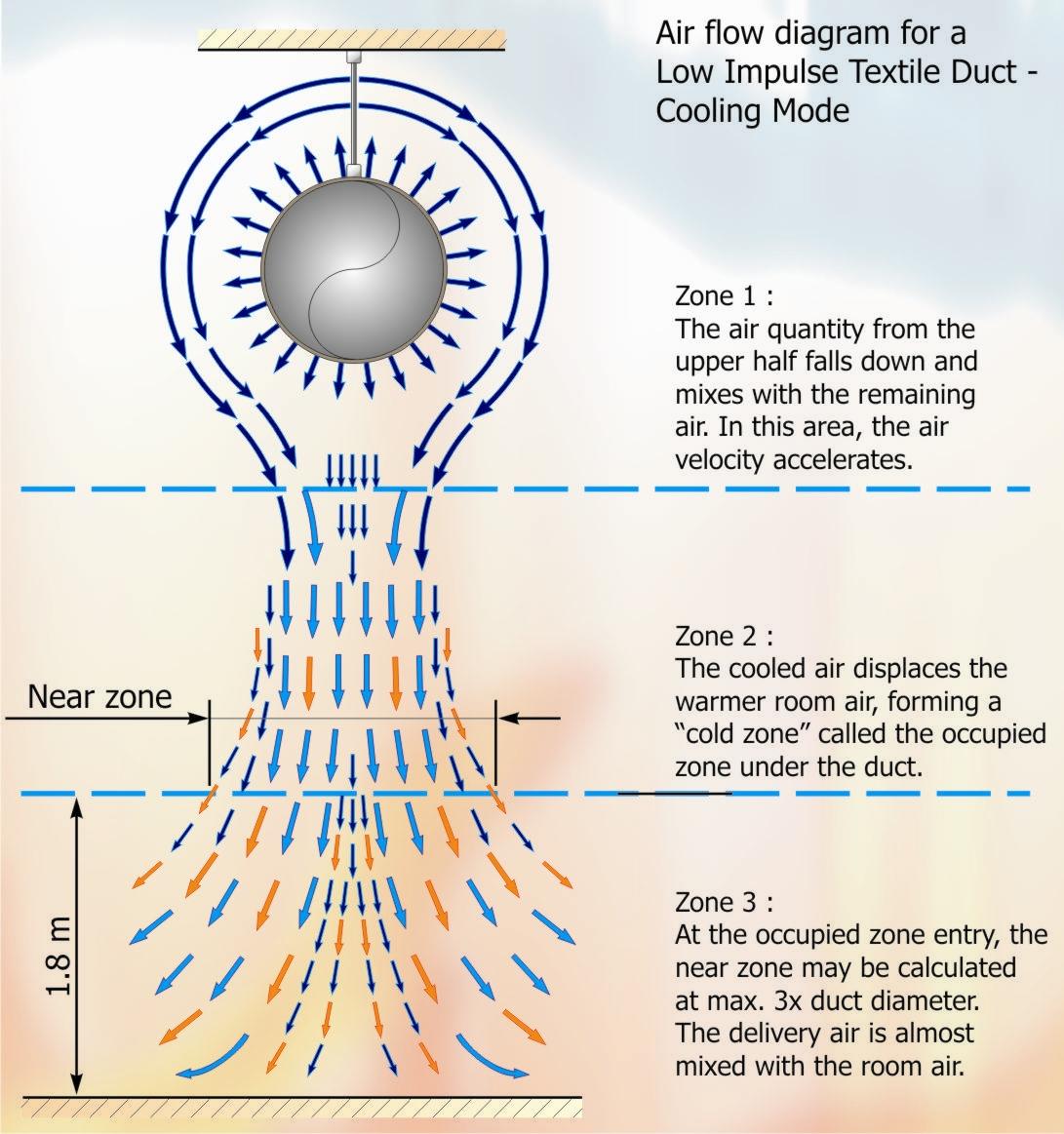
Figure 2 – Air flow diagram for a Low Impulse Textile Duct ~ Cooling Mode.
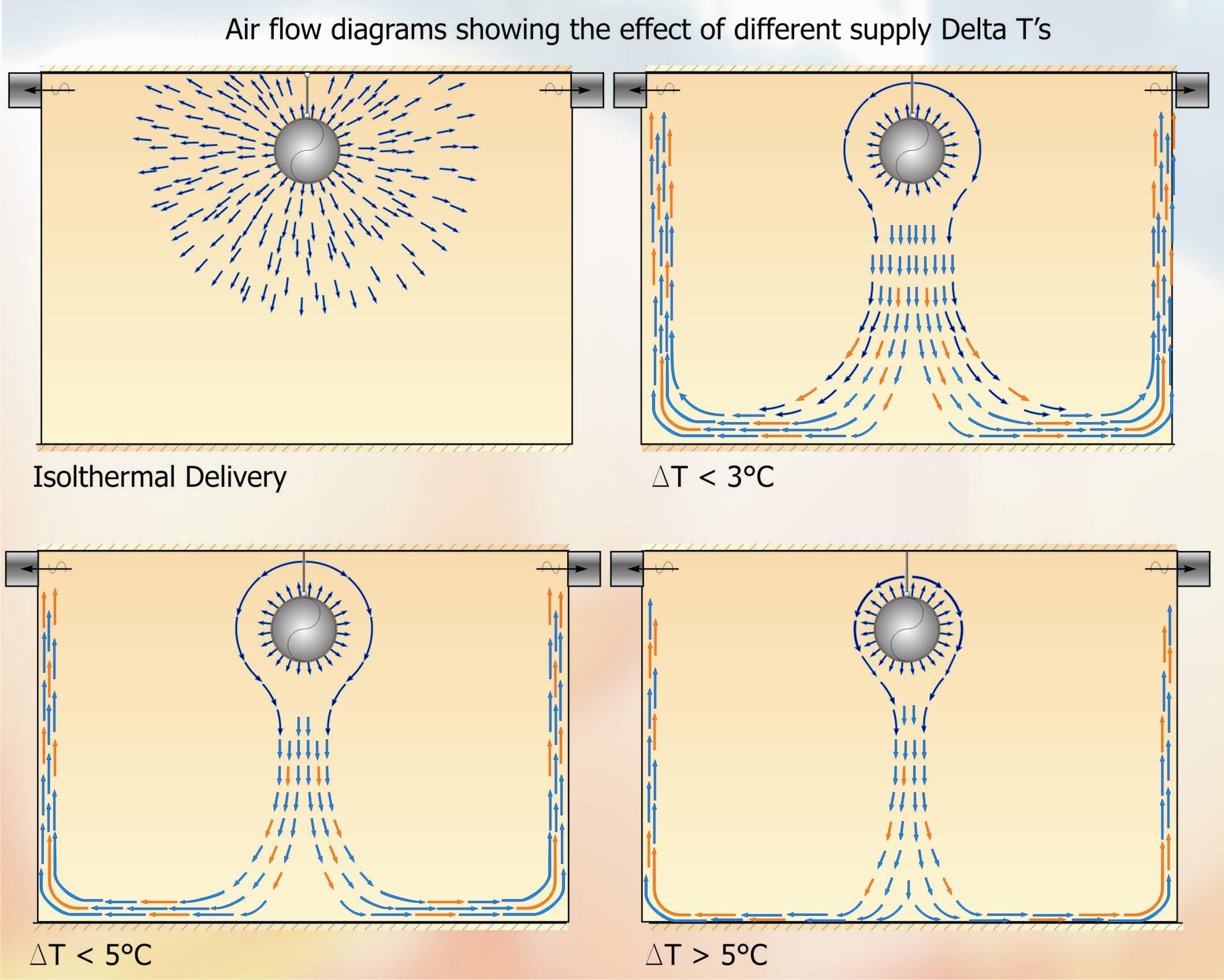
Figure 3 – Air flow diagrams showing the effect of different supply Delta T’s.
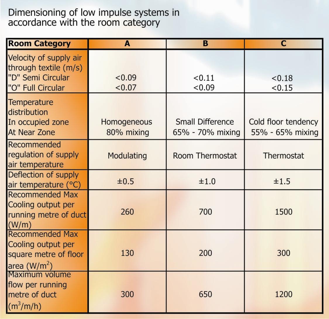
Table 2 – Dimensioning of Low Impulse Systems in accordance with the room category.
___________________________________________________________________________
NEXT VOLUME: Part 44 – Textile Based Air Distribution – continued
DISCLAIMER: Whilst every effort is made to ensure absolute accuracy, Business Edge Ltd will not accept any responsibility or liability for direct or indirect losses arising from the use of the data contained in this series of articles.
