 Cassette Split Systems
 Safety Gloves
 UV Leak Detection
 Condensate Drain Pipe
 Nitrogen Regulators
 Filter Driers
 Filter Cores for Core Shells
MASTERCLASS – AIR CONDITIONING TECHNOLOGY
Volume 44 – Textile Based Air Distribution Pt2
In last month’s article (Volume 43) we commenced a 4-Part Study of Textile Based Distribution Systems. We now continue with VOL 44 in this module dedicated to an unusual form of air distribution technology.
Textile Based Air Distribution
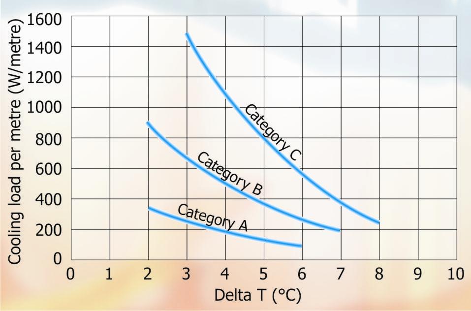
Figure 1 – Room Category Comfort Chart.
Chart for Low Impulse system – cooling.
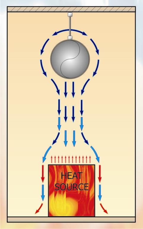
Figure 2 – Room Normal heat distribution.
Figure 2 shows cooling air distribution for normal heat load in situations where a very even temperature is required across the plan of the area resulting in a very homogeneous conditioned environment.
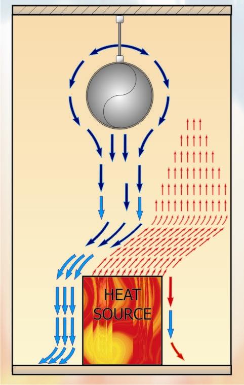
Figure 3 – The Conflict between a very high heat source and low impulse.
Figure 3 shows what can happen if the heat source is of a considerable size and the result of which is that the falling cooling air currents ‘ricochet’ off the rising heat convection currents. This can cause draught as all the cooling air falls to one side of the heat source. The way in which this can be over come, is to have the low impulse ducts to one side of the heat source and in this way the cooling air then displaces the warm air. This equates to an efficient set up whereby 1 kW of cooling may overcome 1.5 kW of heat load.
“D” semi circular textile ducts as oppose to the full circular ducts are used in applications where the headroom is limited, say to 3,000 mm, or when 100 % turn down is required on a variable air volume basis. The full circular type can accept a turn down in volume of up to approx. 60 % of the full volume providing that the system is designed with this in mind, as the static pressure in the furthest runs of textile ducting must remain at approx. 60 Pa.
High Impulse
The supply air jets out of the specific pattern of holes at between 10 m/sec and 15 m/sec depending on design parameters and without noise irritation. The system has the ability to draw in 20 to 40 units of room air relative to 1 unit of supply air, this rated at a distance of 3,000 mm away from the duct. To provide a comparison, a traditional nozzle draws in 12 – 15 units of room air relative to 1 unit of supply air.
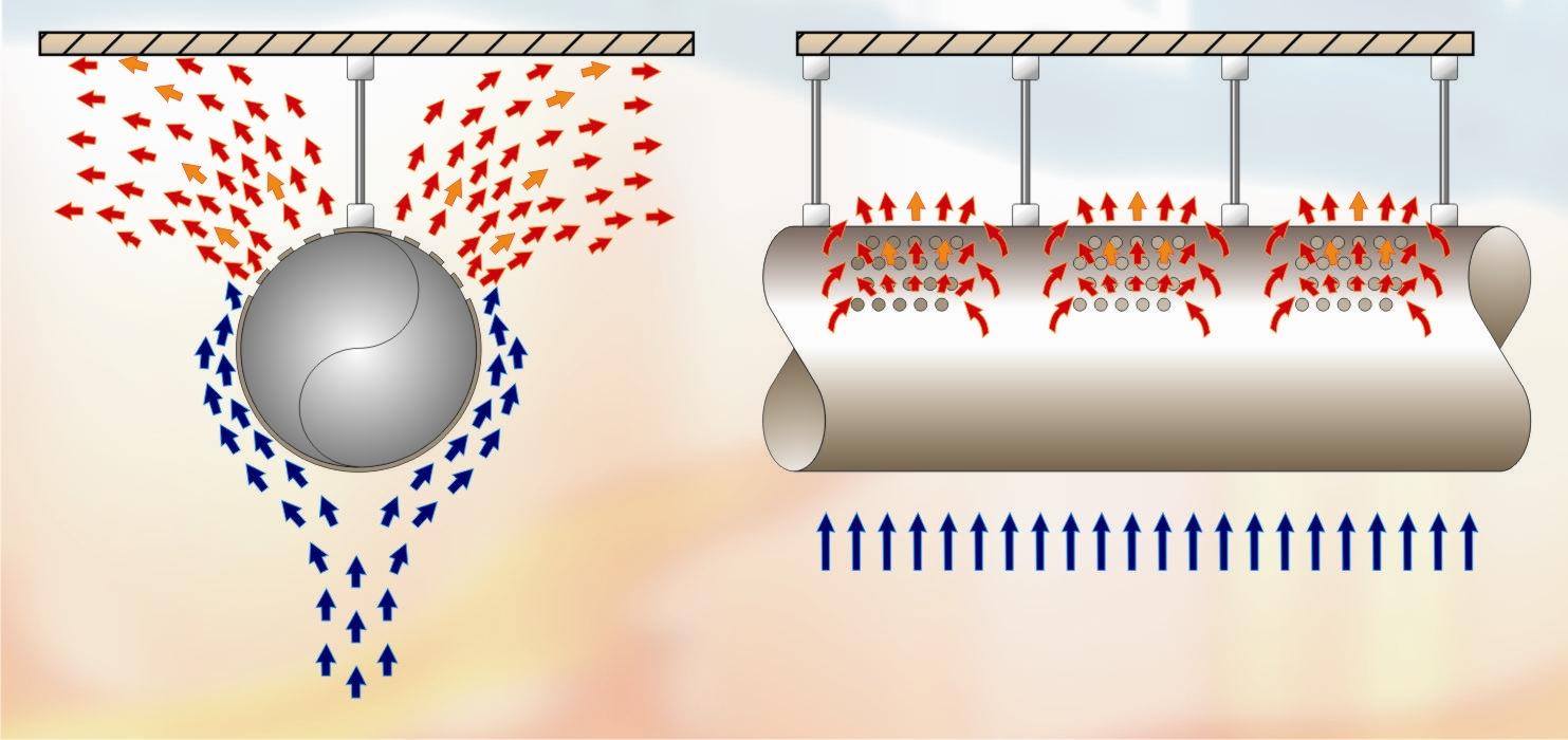
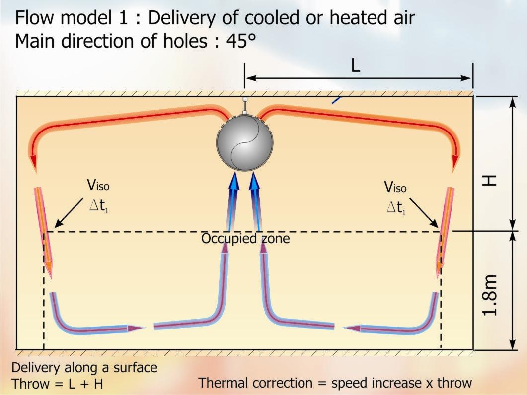
Figure 4 – Air flow around a High Impulse duct – Mixing & Induction
The high velocity of the air through the patterned holes provides the momentum for the system to push the air across the room and down into the occupied zone, even when the holes are uppermost or pointing in the directions of 3.00 & 9.00 O’clock. The supply air soon becomes mixed with the drawn in room air, see figure 4, a braking action takes place and by the time the mixed air enters the occupied zone it will have slowed down significantly so that the specified comfort conditions are achieved. Whilst this air is being pushed, the high discharge velocity is drawing air to flow upwards from the occupied zone by the ‘Venturi Action’ since a low pressure is created below the duct. The two air movements meet and a room air circulation is set up creating a very homogeneous room environment, see Figure 5.
Low air movement is rarely more critical than in a swimming pool hall, as the wet bathers are very susceptible to draught and too higher an air movement over the pool water will lead to higher rates of pool water evaporation. Air movements around the poolside and above pool water should be around 0.1 m/sec.
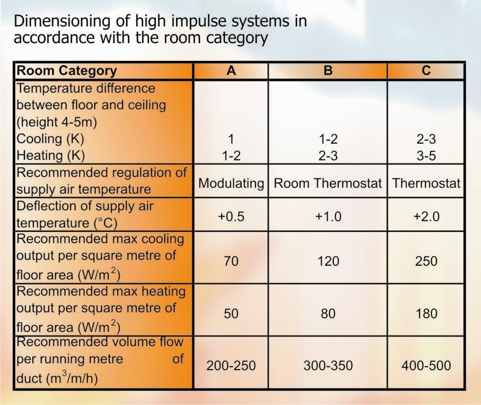
Table 1 – Dimensioning of High Impulse Systems in accordance with the room category
NEXT MONTH: Vol 45 – Textile Based Air Distribution – Pt3
DISCLAIMER:
Whilst every effort is made to ensure absolute accuracy, Business Edge Ltd. will not accept any responsibility or liability for direct or indirect losses arising from the use of the data contained in this series of articles.
