 Cassette Split Systems
 Safety Gloves
 UV Leak Detection
 Condensate Drain Pipe
 Nitrogen Regulators
 Filter Driers
 Filter Cores for Core Shells
This section deals with Free Cooling equipment specifically designed for next generation switch-room applications, which are tolerant of wider variations in temperature and humidity than other applications. This type of cooling provides a cost effective alternative to Mechanical DX Cooling or water-glycol based cooling systems.
The use of full fresh air free cooling dispenses with the need for Mechanical DX Cooling or water-glycol based cooling. This provides an advantage where there is a desire to eliminate the presence of refrigerants, preferring to maximise on natural cooling methods.
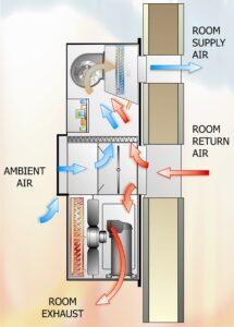
The General Arrangement for such equipment is shown in Diagram 1.
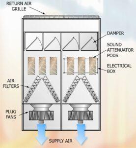
These units simply comprise the following key components and are available in upflow or downflow configuration:-
- Fresh Air Damper
- Sound Attenuator Section
- High Efficiency Air Filters
- Plug Fans
- Insulated and Sound Attenuated Casing
There are 2 modes of operation:
Recirculation Mode during start-up
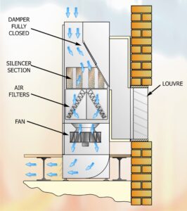
On start up, a fan is energised and the outside damper is driven to 50% which enables the outside air to be monitored to ensure the rate of change of temperature within the room is less than 0.5 deg C per minute averaged over 5 minutes before opening fully. In downflow configuration the re-circulated room air is drawn through the grilles in the top of the unit. Fresh air is drawn in from the back of the unit and mixes with the re-circulated air, which then passes into the room via the floor void.
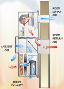
Normal Operation
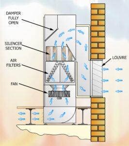
The outside air damper is motored fully open to allow full fresh air to be drawn through the louvre and discharged into the room via the floor void. Room exhaust air is then expelled via pressure relief dampers / flaps which are external to the unit. This alleviates over-pressurisation of the room and expels accordingly to maintain the desired room pressure. These are weighted dampers, which can be set to develop a specified room pressure.
Since the fresh air temperature is subject to wide variation over a 24-hour period and across seasonal variations, it is essential to vary the amount of fresh air being supplied to the conditioned space in order to maintain the setpoint space temperature. The Plug Fans are fed via multi-tap transformers which allow them to be run in low or high speed mode via the controller.
The Unit is controlled by a remote room Temperature Sensor, which monitors the Next-Generation Switch Room condition and a Fresh Air Temperature Sensor mounted in the rear of the Unit. The combination of both sensors operates the Fresh Air Damper and sequences the Fan stages On or Off. Fan Operation is as follows:
| Plug Fan 1 | Speed | Plug Fan 2 | Speed | |
| Stage 1 | On | Low | Off | Off |
| Stage 2 | On | High | Off | Off |
| Stage 3 | On | High | On | Low |
| Stage 4 | On | High | On | High |
The unit controller has a sequence operation to ensure equal fan run hours.
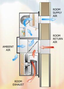
Packaged Units
Diagram 8a, 8b and 8c.
These Packaged Close Control Units are designed to ‘clip on’ to exterior walls of containers or Portacabins containing telecommunications switch equipment. These units comprise Full Free Cooling, Incremental and Full Mechanical DX Cooling capability and function in generally the same way as Fresh Air with Supplementary DX Cooling Units described above.
The 3 modes of operation are shown in Diagrams 4, 5 and 6.
NOTE: Our sincere thanks go to Mike Creamer of Business Edge Ltd for this article.
DISCLAIMER: Whilst every effort is made to ensure absolute accuracy, Business Edge Ltd. will not accept any responsibility or liability for direct or indirect losses arising from the use of the data contained in this series of articles.
