 Cassette Split Systems
 Safety Gloves
 UV Leak Detection
 Condensate Drain Pipe
 Nitrogen Regulators
 Filter Driers
 Filter Cores for Core Shells
Vol 22 – Control, Safety & Protection Devices used in the Vapour Compression Cycle
Author Mike Creamer, Business Edge Ltd
AIR CONDITIONING TECHNOLOGY
PART 22
Control, Safety & Protection Devices used in the Vapour Compression Cycle.
In the last two month’s volumes 20, 21 we considered the containment of refrigerant in vessels and refrigerant lines coupled with safety and the various methods to meet these requirements. This month we move on to Control, Safety & Protection Devices used in the Vapour Compression Cycle.
Control of Space Temperature
An air conditioning system is designed and installed to control the required temperature and humidity levels in conditioned spaces such as offices, theatres, restaurants, manufacturing and assembly areas and many other applications. Temperature and humidity control is also required in refrigerated display cases and coldrooms used in supermarkets as well as smaller enclosures such areas such as the household refrigerator.
The desired conditions in the aforementioned areas are maintained or controlled by devices known as ‘operating controls’.
The air conditioning equipment or system is allowed to operate within safe and correct levels of pressure, temperature and other parameters by safety or ”limit controls”. These controls primarily prevent damage to the system and potential injury to people through system malfunction.
Refrigeration and air conditioning control systems can be divided into 3 sections:
Conditioned area:
The area in which temperature, perhaps also humidity and in some instances, pressure, is being controlled.
Controlling product:
Instruments with sensing devices that is responsive to changes. These include for example thermostats, pressurestats and humidistats.
Operating unit:
Cooling, heating, humidification or dehumidification equipment that is regulated by the controlling product and directly affects the controlled conditions via control of valves, dampers, fans, compressors, etc.
A ‘closed loop (feedback) control system’ is one which constantly corrects the conditions within it. In the operation of a typical air-conditioning or refrigeration system, the thermostat is the controlling product, the compressor is the operating unit and the room, display case or refrigerator is the conditioned area. The following is a simple example of a closed loop control system:
When the conditioned area temperature rises, the thermostat turns the compressor on, this then circulates the refrigerant so that it can cool the conditioned area to within the setpoint limits. When sufficient cooling has been applied, the controlling product turns the compressor off. When the air-conditioned area or refrigerator rises in temperature, the above cycle is repeated.
The controlling product
The majority of today’s refrigeration systems are fully automatic in operation and incorporate control and safety limit devices which are mechanical, electro-mechanical or electronically controlled in their operation.
There are several different types of controlling product that can be used to help maintain the desired temperature and humidity conditions in the controlled area. The following are a few of the most common options:
- Compressor controllers
- Temperature operated switches (thermostats)
- Pressure operated switches (pressurestats)
- Heating controllers
- Limit thermostats
- Modulating valves (mechanical or motorised)
- Humidity controllers (Humidifiers & Dehumidifiers)
- Humidistats
- Dewpoint controllers
The following controlling products can be used to achieve the required operating parameters of the refrigeration system itself:
Head pressure controllers (for Low ambient control)
- Pressure operated condenser fan speed controllers
- Temperature operated condenser fan speed controllers
- Condenser liquid level back-up valve (pressure operated)
Refrigerant flow devices
- Reversing valves
- Check valves
- Solenoid shut off valves
- Modulating valves (motorised)
Controls will fall into one of three categories:
- Cycling controls
- Manual reset controls.
- Modulating controls
A cycling control is one that conducts an operation at the desired setpoint and automatically ceases this operation when no longer required.
A manual reset control is one that conducts an operation at the desired setpoint but will not cease this operation until an external action is applied such as a person pressing the manual reset button on a High Pressure cut-out switch.
A modulating control is one that continuously makes fine or coarse adjustments to the current operation in order to precisely maintain a desired condition or setpoint.
In the following sections, we look at a number of the aforementioned controlling devices:
Compressor Controllers
There are three basic types of cycling switches used for control of compressor operation:
- Temperature (thermostatic switch)
- Pressure (pressure switch)
- Microprocessor Controller (sensor + relay or triac)
Temperature Controller – Thermostatic Switch
The temperature controller can simply close contacts at a temperature above the desired setpoint in order to operate the compressor, thus providing cooling until the desired setpoint has been re-established. In order to prevent excessive cycling, a differential of say 2K should be incorporated into the controlling product. For example, at a setpoint temperature of 20 Deg C, the compressor would be switched on as soon as the temperature at the sensor rises just above 20 Deg C. The compressor would continue to operate and provide cooling until the temperature at the sensor falls to 18 Deg C. After compressor shut down, the temperature would slowly rise due to continuous heat gain to the conditioned space until a temperature just exceeding 20 Deg C is again experienced. This ensures that the number of starts per hour for the compressor does not exceed the manufacturer’s recommendations. However, precision temperature control to better than +/- 2 K is not attainable under these circumstances.
A typical pressure operated thermostatic switch is shown in Figure 1.
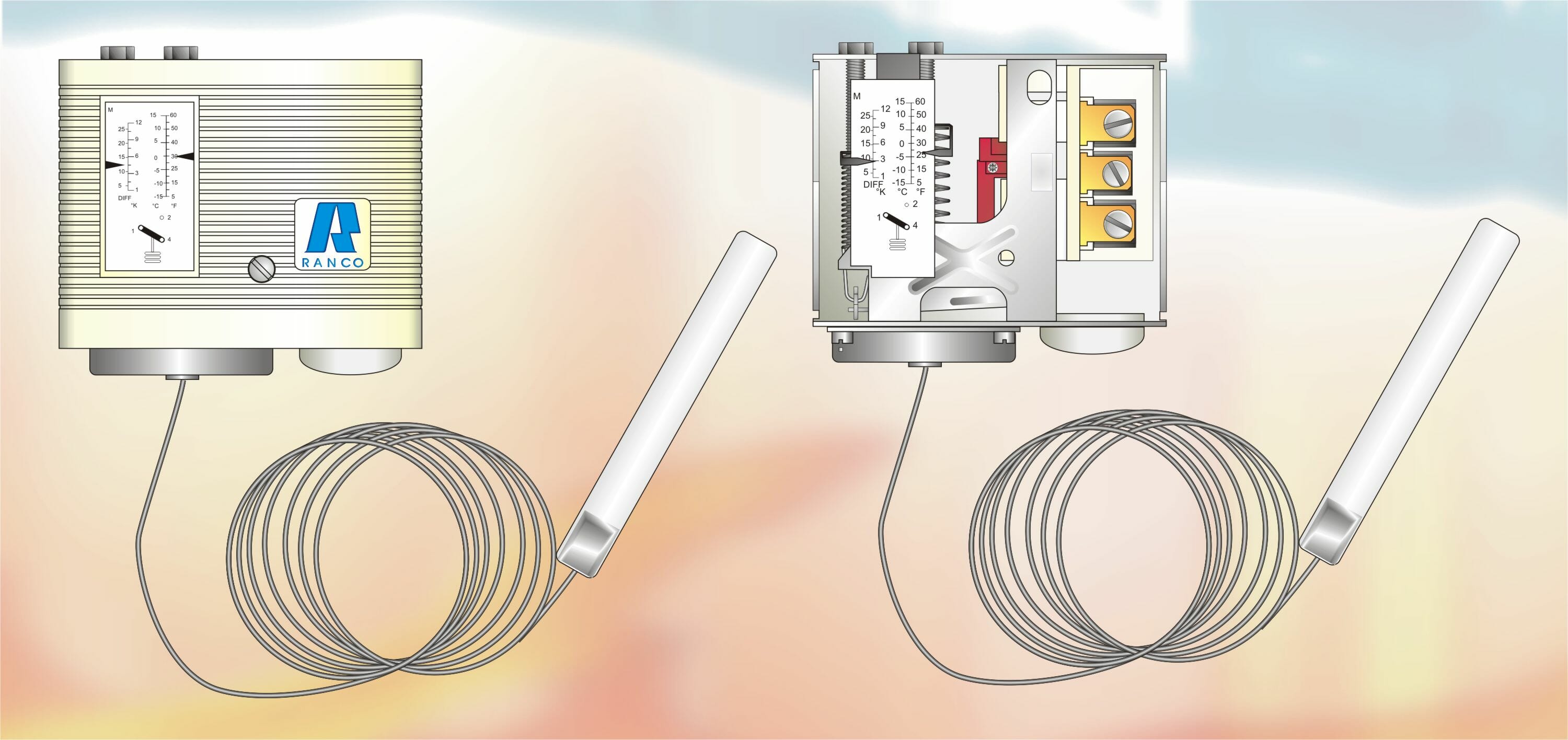
Figure 1
“A Pressure Operated Thermostatic Switch with remote sensing bulb. Operating Range -15 to +15 Deg C & Differential Range 1.0 – 12 K.
The setpoint range of this particular model is -15 to +15 Deg C with an adjustable temperature differential range of 1 to 12 K. Adjustment of the setpoint and differential range is made via the two screws located on the top of the switch housing. The switch incorporates changeover electrical contacts which permit the switch either close (usual for cooling applications) or open an electrical circuit on a rise in temperature above the setpoint.
The remote sensing bulb located at the end of the capillary tube allows the switch to be positioned in a safe and accessible location remote from the point being sensed. The remote bulb contains a small charge of refrigerant which exerts a variable pressure on a diaphragm within the switch Adjustable spring pressure opposes the movement of the diaphragm. The operation of this type of mechanism has been adequately described in the section covering expansion valves.
Pressure Controller – Pressure Switch
A pressure switch fitted to the low pressure side of the refrigeration system can be used very effectively to control compressor operation. The low pressure switch is also used to protect the compressor. A system might therefore be fitted with two low pressure switches although this is not usually necessary. The following describes various ways in which a low pressure cut-out switch is used:
Pressure Switch – for control of compressor operation
In the case of a fixed speed compressor, an increase in thermal load at the evaporator will cause an increase in evaporator pressure. This effect can be sensed by the Low Pressure Switch and used to switch on the compressor as soon as the pressure setpoint has been exceeded. The compressor will be allowed to run at full capacity thus reducing space temperature. Since the system capacity will be equal to or in most cases greater than the duty / load, the pressure at the evaporator will fall as the load falls in relation to capacity. When the pressure falls below the setpoint of the low pressure switch, the compressor will cease to operate.
The compressor will resume operation when the mechanical differential within the low pressure switch has been traversed.
The mechanical differential within the low pressure switch will ensure that the compressor does not cycle too frequently. Low cost pressure switches have a pre-determined set point and differential. Others have an adjustable setpoint and an adjustable differential pressure range.
The setpoint pressure is determined by relating the pressure to the saturation temperature of the refrigerant in the system. An allowance will be made for the difference between the saturation temperature and the realised space temperature, which will always be higher.
The differential setting will be determined by the allowable temperature swing within the space in relation to the saturation temperature of the refrigerant.
Alternatively, the setpoint and differential values can be set by trial and error during the commissioning stage until the desired space temperature has been attained.
Pressure Switch – for compressor and system protection – Low Pressure Cut-Out
If the saturation temperature falls below a given level, freezing will occur at the evaporator. Whilst this may be acceptable for refrigeration systems that are designed to control frozen food at say -18 to -21 Deg C, this will be totally unacceptable for a comfort or close control air conditioning system.
Since the evaporator temperature is governed by the saturation temperature of the refrigerant which in turn is governed by the saturation pressure in the low side of the system, a low pressure switch can be applied and set to cease compressor operation below a certain pressure.
If the evaporator were allowed to form frost on the tubes and fins, system performance and efficiency would decline and the frost / ice would also act as an insulation to heat flow from the air to the refrigerant. Excessive frosting would lead to inadequate evaporation of the liquid refrigerant within the evaporator, which then might travel to the compressor resulting in liquid slugging and compressor failure. The low pressure switch can therefore be applied to prevent this situation arising.
Potential refrigerant leakage from any system must also considered. Whilst every effort is made by every conscientious and competent engineer to avoid this, there will inevitably be minor or major leaks from some systems. In the event of a leak, the entire refrigerant charge will be lost to atmosphere if this goes undetected. Whilst any liquid refrigerant is present, the pressure in the system will remain constant for a given temperature. The compressor may also be required to run during such circumstances.
A continuous leak whilst the system is operating will initially lead to incorrect operation which will show as low discharge pressure, low suction pressure, partial frosting of the evaporator, reduced running current, increased superheat and other symptoms. A progressive loss of cooling capacity will also result and the system will then continue to run for prolonged periods as a result of it’s inability to satisfy the required space temperature. Whilst the compressor motor will have a reduced load and will be drawing less running current, the mass flow of refrigerant passing over the motor windings will steadily reduce resulting in a steady increase in motor temperature. This might reach a point where the compressor motor either shuts down via motor protection devices or the motor fails completely resulting in a burn-out.
The low pressure switch can eliminate all these problems if the setpoint is set correctly.
Microprocessor Controller
Microprocessor controllers are theoretically capable of controlling to a setpoint with no differential. However, in order to meet the limitations of the equipment being controlled, a differential is introduced via the controlling software. Microprocessors are extremely powerful in the field of control, safety and protection but due to their complexity, these will be the subject of a future article.
These controls provide both range and differential adjustments for accurate control of the refrigeration cycle. When larger systems are controlled by these products, a relay and/or contactor is needed between the control and the compressor motor because the controls are not designed to handle very starting and running current loads.
Pressure Controls
There are two main types of pressure control available to system designers:
– Customer adjustable [figure 2 & 2a]
– Factory pre-set [figure 3]
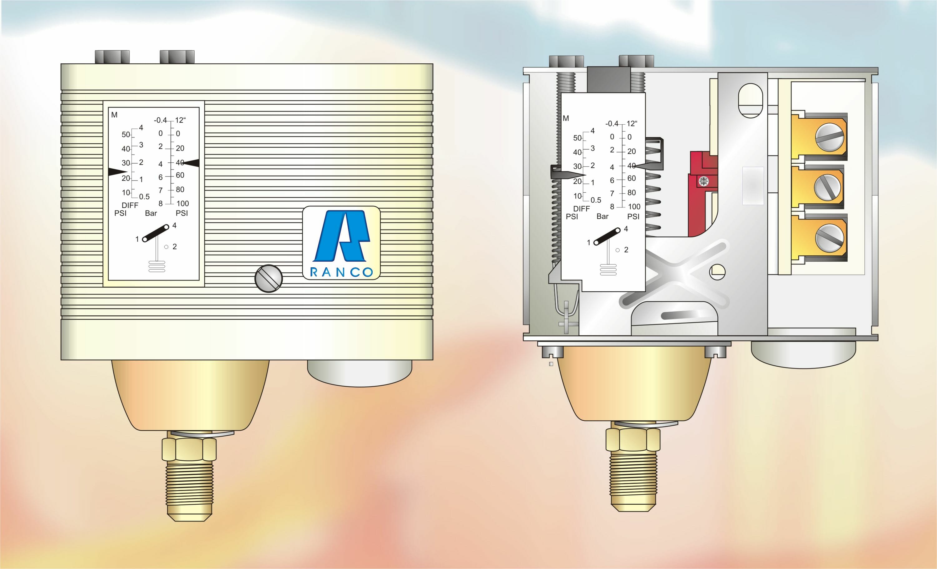
Figure 2
“A Low Pressure Cut-Out Switch. Operating Range 0 – 7 bar & Differential Range 0.5 – 4 bar”.
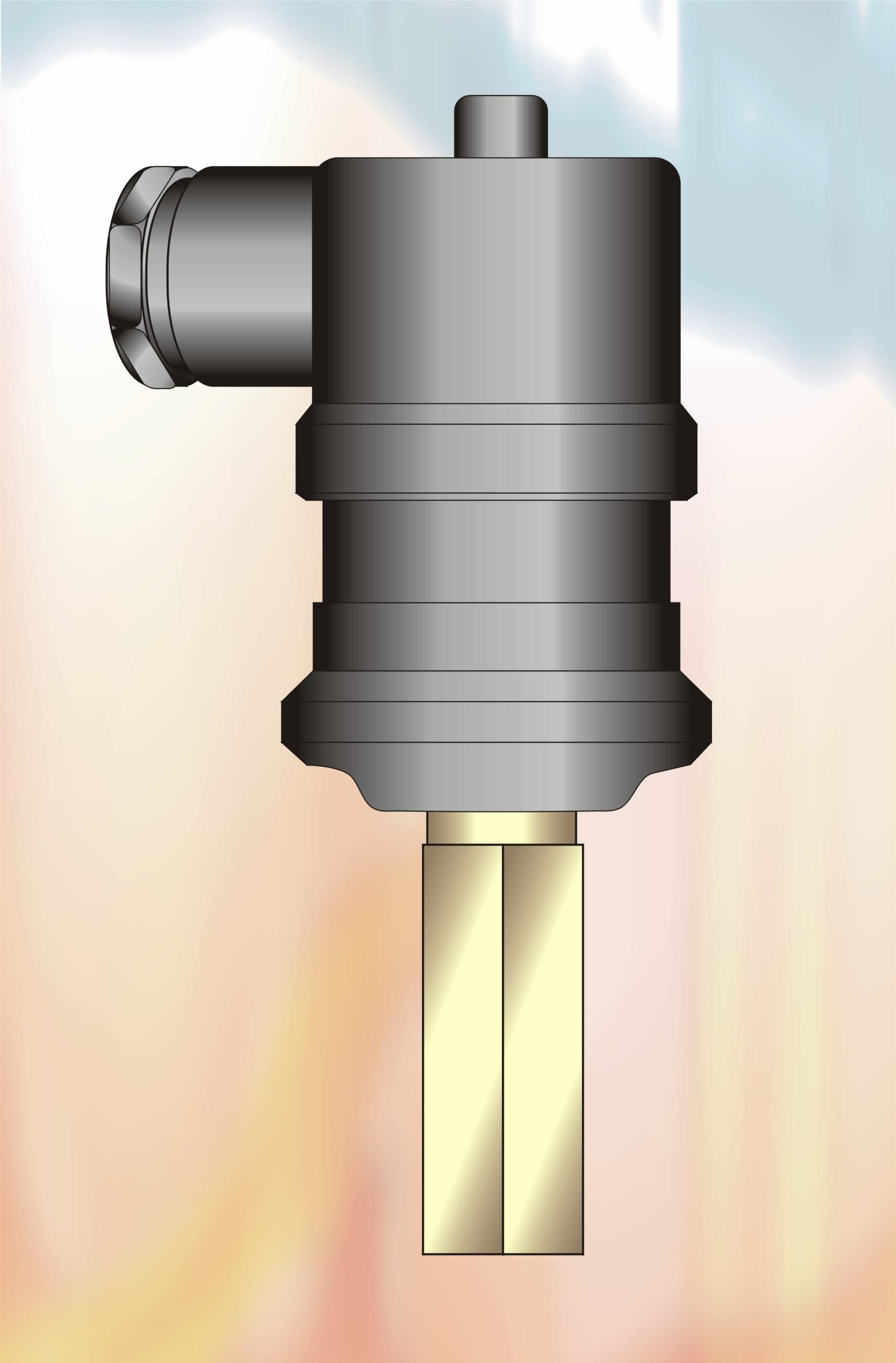
Figure 3
“A Low Pressure Cut-out switch with factory preset values for operating setpoint and differential with manual reset facility”
Both of these products are available as automatic reset or manual reset and in various pressure setting ranges to suit all types of air-conditioning or refrigeration systems.
The following Table includes shows typical information that a Manufacturer would supply of their Controls range to aid selection.
Table 1
| High or Low | Reset | Range | Differential | IP Rating
|
Bellows Type
|
|||
| psig(bar) | psig(bar) | 33 | 44 | 66 | Standard | T.Ü.V | ||
| Low | Auto | 10” to 100 | 9 to 57 | · | Yes | |||
| (-0.3 to 7) | (0.6 to 4) | · | ||||||
| Low | Manual | 10” to 100 | 9 fix | · | Yes | |||
| (-0.3 to 7) | (0.6 fix) | · | ||||||
| High | Auto | 100 to 435 | 35 to 115 | · | Yes | |||
| (7 to 30) | (2.5 to 8) | · | ||||||
| High | Manual | 100 to 435 | 45 fix | · | Yes | |||
| (7 to 30) | (3.2 fix) | · | ||||||
| High | Auto | (7 to 30) | (3 to 8) | · | Yes | |||
| · | ||||||||
| High | Manual | (7 to 30) | (3.2 fix) | · | Yes | |||
| · | ||||||||
| High | Manual | (7 to 30) | (3.2 fix) | · | Yes | |||
| · | ||||||||
| Tolerance | Pressure Differential | Tolerance | T.Ü.V | |
| Vac – 75 psi | ± 2 psi | 7 – 15 psi | ± 3 psi | |
| Vac – 75 psi | ± 2 psi | 20 – 35 psi | ± 4 psi | |
| 50 – 100 psi | ± 4 psi | 40 – 55 psi | ± 7 psi | |
| 100 – 180 psi | ± 4 psi | 50 -70 psi | ± 7 psi | Yes |
| 150 – 250 psi | ± 4 psi | 70 – 110 psi | ± 10 psi | Yes |
| 250 – 350 psi | ± 6 psi | 100 – 140 psi | ± 14 psi | Yes |
| 340 – 450 psi | ± 10 psi | 120 – 180 psi | ± 14 psi | Yes |
| 400 – 450 psi | ± 10 psi | 150 – 200 psi | ± 16 psi | Yes |
These controls can be used as pressure cycling controls and safety limit controls depending on their position in the system.
A low pressure cycling control is positioned on the suction side of the compressor and is used as the operating control to cycle the compressor as illustrated in Figure 4. By sensing the suction pressure, the control can regulate the evaporator temperature.
Figure 4
NEXT MONTH: Volume 23 – Control, Safety & Protection Devices used in the Vapour Compression Cycle continued.
DISCLAIMER: Whilst every effort is made to ensure absolute accuracy, Business Edge Ltd will not accept any responsibility or liability for direct or indirect losses arising from the use of the data contained in this series of articles.
