No products in the cart.

MASTERCLASS – AIR CONDITIONING TECHNOLOGY
VOL 46 – Textile Duct Final Word
In the previous article (VOL 45) we continued with our Study of Textile Based Distribution Systems. We now conclude with the final part in this module dedicated to an unusual form of air distribution technology that is steadily gaining increasing acceptance throughout the Refrigeration and HEVAC industries.
___________________________________________________________________________
It is critical that the textile has sufficient stability to endure the washing process, allowable shrinkage rates should be a maximum of 0.5%. This ensures that the permeability of the textile duct remains within the specified tolerances and that the textile ducts can be successfully refitted after washing (this is critical for semi circular textile ducts)
Colours
The ducts are available in standard colours, however, any colour according to either RAL No. or Pantone No. is possible – a range of approx. 1,600 colours are available. There would be a cost implication for special colour, which could become disproportionate to the overall cost on smaller projects. Standard colours are typically Red, Medium Blue, Yellow and Light Blue for low impulse and Light Grey is available for high impulse ductwork.
Duct Sizes
Standard duct sizes range from 200 mm diameter to 1,600 mm diameter with intervals of approx. 100 mm; however, this does not preclude other sizes.
Precautions
It is important to recognise that a textile duct system is essentially a means of air distribution rather than air filtration. However, the textile duct does have an effective filtration capability. The air handling plant should provide the filtration (to a minimum of F7, BS EN 779 – ISO Eurovent EU7) to ensure that the textile duct does not act as the primary filter. This will increase the time between laundering of the textile duct system. This may seem a high level of filtration but it is becoming more common with the lessening quality of outdoor air and demands for higher quality within the built environment.
It is not uncommon for the end-users to choose the semi circular type over the circular type on the grounds of aesthetics, however, both semi and full circular should be considered carefully. The full circular type can be more practical in circumstances where ceiling height is not a factor. It can also be far more cost effective.
Coloured textile ductwork is recommended since white ducting will eventually show greying despite being clean and safe, as long as there is a man appropriate maintenance regime in place. The manufacturer will provide a “Washing and Maintenance Manual”.
Clean rooms of classification 100,000, 10,000 and 1,000 can be installed with non shedding textile ducting and these are usually white and won’t suffer the greying phenomenon
Textile & Fabric Duct Velocities & Pressures
The following guideline parameters are recommended for sizing a textile duct ventilation system:
- The textile duct inlet velocity should be a maximum of 7 m/s; this velocity also applies to every section of ductwork. This is to uphold the optimum economical design, the benefit of which is the avoidance of wasting fan power whilst minimising duct sizes. There are, however, exceptions to the 7 m/s rule; where a higher velocity is used there must be an equal compensating factor, typically a greater static pressure to prevent textile ductwork fluttering or pulsating.
- When textile ducting is to be combined with rigid ducting to serve noise sensitive areas, such as studios, labs, offices etc, it is usual to work on lower velocities as the rigid ducting may otherwise cause unwanted noise. These velocities are typically between 4.0 to 5.0 m/s.
- The normal static pressure values are between 70 and 125 Pascal. Recommended values are 80 -110 Pascal. These figures do not take account of a Textile Plenum (Header Duct); the header provides a means by which to distribute the air to the various textile ducts. The plenum pressure loss is typically between 45 – 100 Pascal. Therefore, it is conceivable that the External Static Pressure (E.S.P.) required at the entrance to a complete system with a header could be between 115 – 225 Pascal.
- The static pressure for the high impulse systems is often higher than that for low impulse as it is this pressure that determines the throw and mixing performance of the system, typically high impulse duct pressures are 90 – 150 Pascal.
- There is a ratio between static pressure and dynamic pressure that must be applied; the approx. static pressure should be equal to or greater than 2.5 x dynamic pressure (dynamic pressure = 0.5rV2). In long buildings (say, 40m – 100m) which are to have close control conditions, this ratio of the pressures is also very important to achieve even air discharge per each linear metre of textile or fabric duct, typically the ratio needs to be 1:4.5.
Typical Textile Duct Arrangements

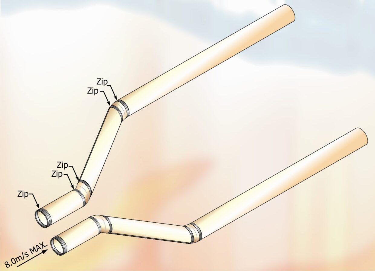
Fig 1 Twin Ducts
Insert Figure 1 Twin Ducts
Figure 1, shows ducts that have 30 to 45 degree bends. This may be for several reasons, for example, to avoid obstructions or to widen the spacing between ducts to achieve an even cover of air distribution. The angled bends, as opposed to 90 degree bends, significantly reduce the pressure loss and save fan motor energy.

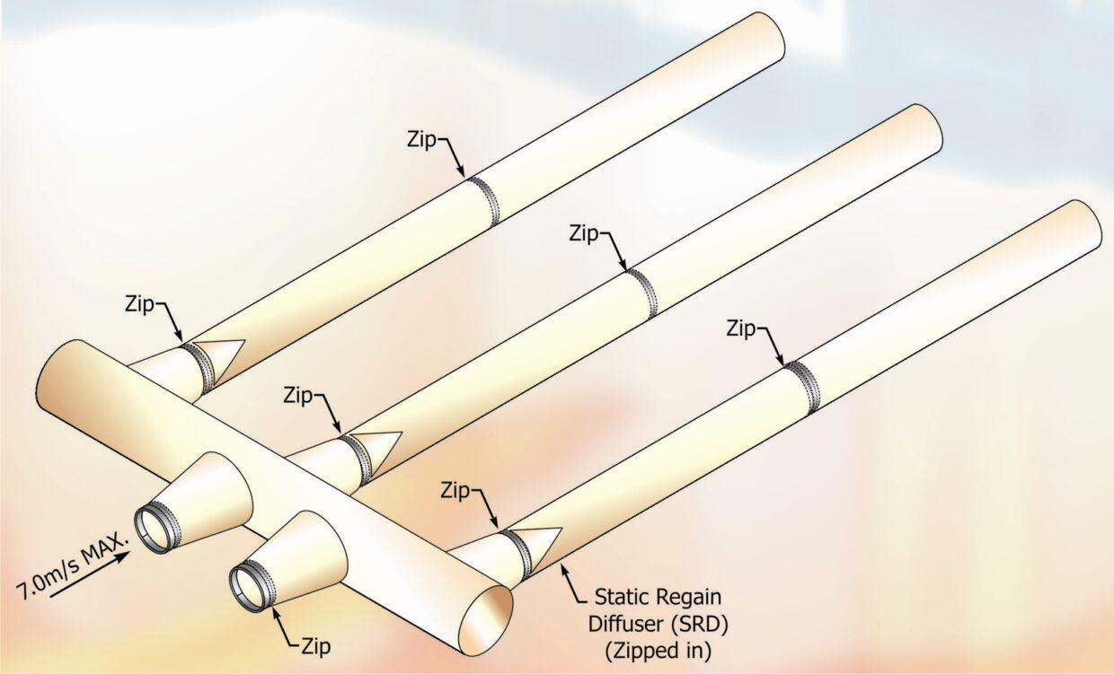
Fig 2 Textile Plenum
Insert Figure 2 Textile Plenum
Figure 2, shows a system that utilises a Textile Plenum (header duct) for the purpose of distributing the air evenly to each textile duct. The Plenum incorporates conical inlet and outlet sockets; these are used as they reduce air turbulence and reduce the pressure loss.

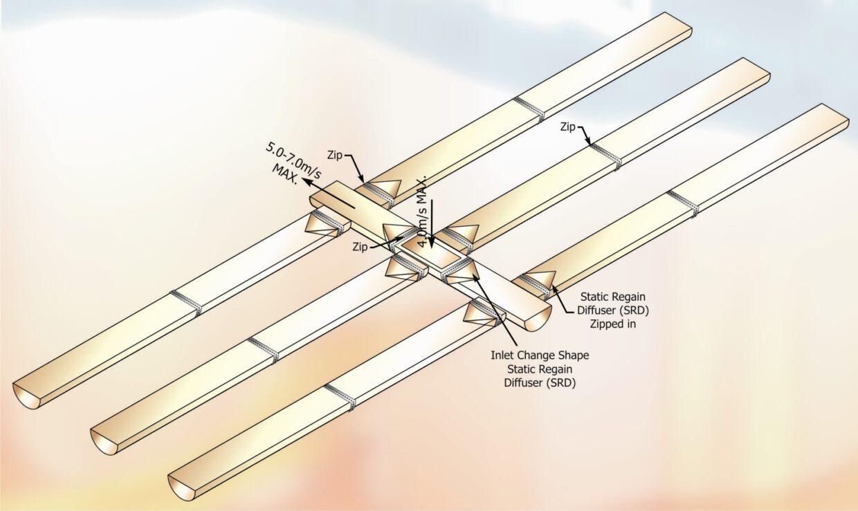
Fig 3 Semi Circular
Insert Figure 3 Semi Circular
Figure 3, shows a semi circular textile duct system with a textile plenum. This system is mounted to the underside of the ceiling. The air from the air handling plant enters the header via a rectangular inlet socket in the roof of the plenum duct. The recommended maximum inlet velocity is 4.0 m/sec. The inlet could equally be circular; however, with only one inlet socket this could be limiting or more costly.

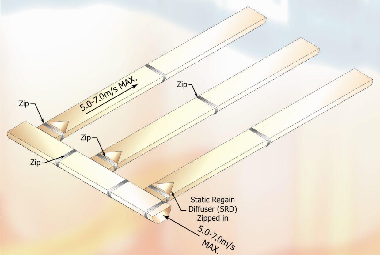
Fig 4 Semi Circular
Insert Figure 4 Semi Circular 2
Figure 4, shows a semi circular textile duct system with plenum that is fed horizontally. Again, the system is mounted to the underside of the ceiling.
General Notes to Typical Textile Duct Arrangements
The velocities indicated are generally recommended Maximums. The minimum velocities are not critical in the same way and these could be taken as half of the maximum velocity. The above figures illustrate the normal positions for zippers and Static Regain Diffusers.
Zippers should be included in the textile duct design to allow for ease of installation and maintenance. Zippers should be positioned every 5 – 10 m depending on size of the textile duct. Zippers may also be required at strategic positions, for example:
- At the inlet connection to facilitate ease of connection to metal supply spigot.
- At an outlet socket from textile plenum (i.e. 90° bend and change of duct size).
- Before and after a duct bend.
- At the position where a Static Regain Diffuser (SRD) is required.
Static Regain Diffusers are conical air straightners that are made from a manmade polyester mesh and are washable in the same way as the textile duct. The SRD fits inside the duct and is therefore not visible from the outside. The air flow in the ducts passes through the mesh which acts to even the air flow velocity profile inside the duct and therefore reducing air turbulence.
Laundering
Textile and fabric ducting offer the benefits of being easily removed and washed in a standard washing machine. Laundering is typically carried out once a year following the instructions provided by the manufacturer. This frequency of cleaning is very similar to that of rigid ducting in compliance with the directives of the Health and Safety Executive. Increased frequency of laundering may be necessary depending on the airborne contamination level and the grade of the filtration used in the air handling unit. Applications for the food industry may require washing of textile ducts to be carried out more frequently.
To facilitate laundering and maintenance it may be required to have at least one of each different textile duct size and type held in stock as a replacement. This is particularly relevant to buildings that operate continuously and where maintaining the environment is crucial. Sufficient textile ducts should be operational to ensure that the specified design room conditions are met during maintenance and laundry.
Suspension systems
This should be selected from the manufacturer’s range to best suit the application. The suspension system should allow for the ducts to be easily removed with minimal interruption to the room’s operation. The materials used for the suspension systems should take into account the room’s environment and any cleaning methods/agents. Anodised aluminium profiles are now most commonly used.
For installation where access is not easy due to machinery, equipment and the like, it can be very pertinent to choose a suspension system that allows the textile duct to slide as it is not always practical to access every metre of the suspension system.
Information required for System Design
- Plan view with dimensions.
- If heating, side elevations with dimensions.
- Room and supply temperatures.
- Air volume flow rate – intended.
- External static pressure.
- Type of Air Handling Plant and preferred location.
- The purpose of the area.
- The activity of the room occupants.
- What room environmental conditions are required.
Delivery to Site
The system is delivered to site as a complete kit and the suspension system should already be cut to length. Once the suspension system has been installed the textile or fabric ducts simply require sliding onto the track, rather like a modern sail into the channel of the mast. If the system is any more complex than separate straight ducts then drawings will have to be provided to show the layout along with dimensions. Also, with every delivery there will be mounting and washing instructions, the latter must be passed on to the end user. When installing the ducts it is important that the ducts are raised out of the boxes and straight into the suspension track, thereby ensuring that the ducts do not come in to contact with a dirty floor.
NEXT MONTH: Vol 47 – Chilled Water Fan Coil Units
DISCLAIMER:
Whilst every effort is made to ensure absolute accuracy, Business Edge Limited will not accept any responsibility or liability for direct or indirect losses arising from the use of the data contained in this series of articles.
