 Cassette Split Systems
 Safety Gloves
 UV Leak Detection
 Condensate Drain Pipe
 Nitrogen Regulators
 Filter Driers
 Filter Cores for Core Shells
MASTERCLASS – AIR CONDITIONING TECHNOLOGY
VOL 49 – Fan Coil Units
In the last article we covered Fan Coil Units in more detail following our simple introduction. We now continue this subject with the intention of providing a detailed overview of this important approach to air conditioning, which is currently realising increasing popularity.
Fan-Coil Units
In our previous article, we described the various types of fan coil units (FCU’s) in terms of being fitted with either direct expansion (DX) evaporators or chilled water coils. We also compared the pro’s and con’s of each type of system and touched briefly on the subject of capacity control in respect of adjusting plant capacity to match system load.
Variations in system load can have a dramatic effect on the efficiency of the FCU and the comfort conditions within the conditioned space. The temperature within a small space can fluctuate noticeably if the FCU has been oversized or if the design load reduces significantly. For example, if the actual load is 50% of the FCU’s capacity then the time taken to cool the space will be halved. This rapid cooling of the room can be uncomfortable despite the fact that the room thermostat will still be maintaining its set-point temperature.
In order to avoid this rapid swing in temperature between cut-in and cut-out actions of the thermostat, the cooling and heating capacity of the FCU should be adjustable.
On a small DX system the adjustment of capacity is relatively simple and can be achieved by the introduction of either a suction pressure regulator into the suction outlet of the FCU (Fig.1), or by discharge vapour injection directly into the evaporator (Fig.2).
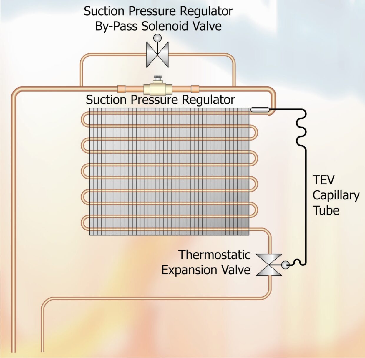
FIGURE 1
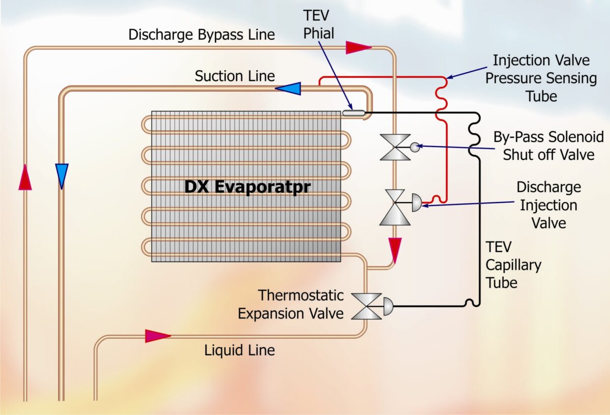
FIGURE 2
Utilisation of either of these methods will result in the temperature within the FCU’s evaporator being artificially increased, effectively reducing the temperature difference between the coil and the air, thereby reducing the coil capacity. However, the suction pressure regulator method may require additional control down-stream of the pressure regulator in order to prevent the compressor switching off on the low-pressure switch.
The discharge vapour by-pass method is fully self-compensating in as much as the suction pressure is increased throughout the system and de-superheating is undertaken by the FCU’s expansion valve. The injection of superheated discharge vapour in between the TEV and its phial causes the phial to sense the increase in superheat and this forces the expansion valve to compensate by allowing more liquid into the evaporator, this increased liquid flow removes the superheat from the vapour.
Capacity control on chilled water FCU’s can be accomplished by regulating the flow of water or adjusting the coil surface area. In Fig.3 the total capacity of the chilled water coil has been subdivided into two circuits 70% and 30% respectively which in effect gives three stages of capacity i.e. 30% or 70% or 100%. Ideally, an electronic temperature controller would be used with this type of system, which would be capable of measuring the rate of temperature change and as a consequence adjust the available capacity to suit the load.
A significant advantage with this type of system is that water flow rates and temperatures do not vary from the design condition over a typical running cycle, whereas regulating the flow rate can increase pressure losses and water temperatures to a point where the system becomes unstable.
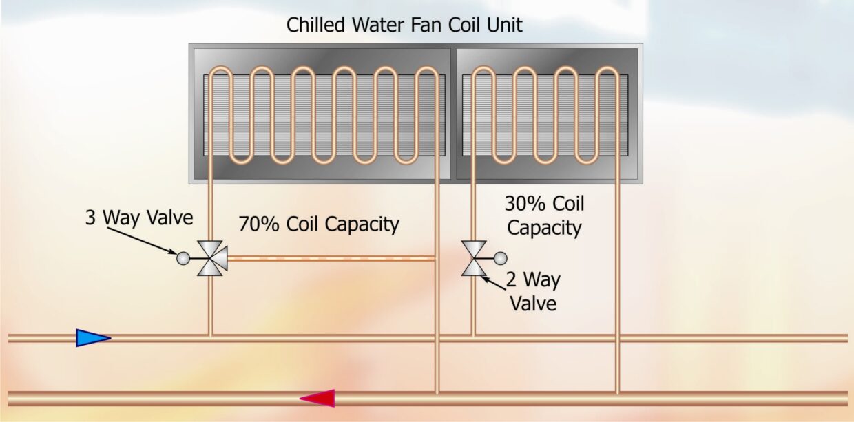
FIGURE 3
The Contractor
Having considered the pro’s and con’s listed above, the contractor will choose to base his proposals on the type of system most suitable for the project. We will assume that he has selected a chilled water FCU system because his application is large and includes a number of separate offices, some of which will require heating whilst others require cooling.
The next decision to be made is the type of piping arrangement to be employed. The options available are, (A) a two pipe system with electric heating, (B) a two pipe system with arbitrary fixed cooling or heating, (C) a three pipe system using low pressure hot water or (D) a four pipe system which incorporates two circuits, one low pressure hot water and one chilled water.
- A two pipe system with the FCU’s fitted with electric heater batteries are generally used on applications where, for the majority of the time, the system is required to provide cooling with heating only required on occasion. The cost of fitting a low-pressure hot water system under these circumstances would not be justified. However, the cost of running heavy duty wiring to each of the FCU’s and if necessary increasing the power supply to the building must be taken into consideration. This type of system can be the lowest cost option if sufficient power is already available on the site.
- A two-pipe system can be used for both heating and cooling if the change over is an arbitrary decision. With this type of installation there is no cooling available when the system is in heating mode. Within certain constraints this can be the most cost-effective type of installation. The main difference between this system and (A) the previous system, is the use of a hot water boiler to provide heating during the winter.
- The three pipe system is frequently used where there is distinct heating / cooling requirements, in as much as the user requires cooling only during the summer months and heating for the remainder of the year. However, the difference between this system and (B) is that it is possible to provide both cooling and heating under certain limitations, for example, when the main requirement is for heating the number of FCU’s which have to provide cooling will represent less than 20% of the total installation. Conversely, when the main requirement is for cooling, less than 20% of the total system should be in heating mode. The advantage with this type of system is the capital cost saving due to the FCU’s requiring a single coil through which either hot or chilled water is fed. However the running cost of this type of system will be the highest of all the types listed here.
- The most flexible system capable of handling a wide variety of environments is the four pipe system. On large installations, where there could be large load variations due to changes in occupancy or variations in solar heat gain, a number of FCU’s could be in heating mode whilst others are in cooling mode. As there are two distinct circuits, each dedicated to cooling or heating, there would be no adverse effects when say 50% of the FCU’s are providing heating whilst the remainder are cooling. The capital cost of this type of system will be higher than the alternatives, but the running costs will be reasonable when you take into consideration the flexibility of the system.
Since in our opening paragraph we stated that the application was large, with a number of separate rooms, with heating and cooling being required simultaneously, the most suitable piping arrangement to suit the application will be (D) the four pipe arrangement.
If we had been planning to use a two or three pipe system, in which both hot and chilled water would flow through the same pipes, dependant on the requirement of the conditioned space, then the chilled water flow rates would determine the pipe sizes. The reason for this is that to remove 1 kW of heat energy, a greater mass of chilled water is required than the amount of hot water required to add 1 kW of heat to a space. This apparent contradiction is simply due to the fact that chilled water coils normally operate with temperature differences (air on to water) of between 10°C and 20°C, while hot water coils work with temperature differences (Air on to water) of between 40°C and 80°C. Moreover, the temperature range between water on coil and water off coil is different for cooling versus heating operation. Chilled water is normally allowed to be in the range 4 – 8K while hot water coils work in the range 10 – 15K.
FCU Selection
The basis of selection of the FCU’s will be determined by the customer’s main priority, which may be noise levels, capital cost, or future expansion. If noise is the most important factor then selection must be based on minimum fan speed. Capital cost will result in selection being based on maximum fan speed. Future expansion may result in selecting the FCU’s to match the future estimated duty based on maximum fan speed to achieve this load but running the FCU’s at reduced speed to match the existing duty.
Our selection will be based on capital cost being the main consideration and, therefore will be based on maximum fan speed. It is common however, for customers to stipulate minimum cost for certain areas while still requiring these areas to be kept at minimum noise levels.
Note: In addition to selecting the FCU’s at maximum speed the chilled water flow rates must also be calculated to match the maximum duty condition.
Our example is based on maintaining a condition of 21°C db, 15°C Wb. We will base our design on Quartz Chilled Water Ceiling Cassettes model CWCH. Three FCU’s will be fitted in isolated offices, each office having a cooling duty of 6 kW total, 5.41 kW sensible and a heating load of 8 kW. The remaining 7 FCU’s will be fitted in an open plan office, requiring a cooling duty of 62 kW total, 46.5 kW sensible and a total of 75 kW heating.
System Loads
Total Cooling Load = (3 x 6) + 62 = 80 kW
Total Sensible Cooling = (3 x 5.41) + 46.5 = 62.73 kW
Total Heating Load = (3 x 8) + 75 = 99 kW
From the duties shown above we can establish that the Sensible Heat Ratio (SHR) of the conditioned space will be;
SHR = Sensible/Total Heat = 62.73/80 kW = 0.78
With this information we can now select the FCU’s.
TABLE 1 – CWCH 95 (L) 4 Pipe Cooling (kW)
| Range 3 (max speed) |
Low Speed |
Low Speed Med Speed |
Low Speed
Med Speed High Speed |
Med Speed
High Speed |
High Speed | ||||||||
| Range 2 (med speed) | |||||||||||||
| Range 1 (min speed) | |||||||||||||
| Room air on | CW temperature | 0.22 m3/s | 0.30 m3/s | 0.35 m3/s | 0.43 m3/s | 0.50 m3/s | |||||||
| db oC | wb oC | In oC | Out oC | Total | Sensible | Total | Sensible | Total | Sensible | Total | Sensible | Total | Sensible |
| 27 | 19 | 6 | 11 | 5.89 | 4.00 | 7.29 | 5.07 | 7.82 | 5.51 | 8.77 | 6.33 | 9.68 | 7.17 |
| 21 | 15 | 5 | 9 | 4.09 | 3.07 | 5.06 | 3.91 | 5.43 | 4.25 | 6.09 | 4.89 | 6.71 | 5.55 |
| 21 | 15 | 5 | 11 | 3.23 | 2.68 | 4.01 | 3.44 | 4.30 | 3.75 | 4.82 | 4.33 | 5.31 | 4.94 |
| 21 | 15 | 5 | 13 | 2.20 | 2.20 | 2.86 | 2.86 | 3.12 | 3.12 | 3.62 | 3.62 | 4.14 | 4.14 |
We will firstly select the three isolated office FCU’s with a duty of 6kW total and 5.41kW sensible. From Table 1 showing Model CWCH 95 cooling duties, under column 1, room air on, we examine the duties available with ‘air on’ at 21°C db and 15°C wb. Under the maximum speed column and total cooling duty column we find that with chilled water on at 5°C and off at 9°C (Mean water temperature = 7°C) we obtain 6.71 kW total cooling with 5.55 kW sensible content.
This gives a SHR of 5.55/6.71 = 0.827 which is sufficiently close for commercial application.
It should be appreciated that for a given size of chilled water FCU the amount of latent cooling duty is directly proportional to the mean temperature of the water ‘on’ and ‘off’. This can be seen by examining the row below our selection point on Table 01 which shows that with air and water ‘on’ as previously stated but leaving at 13°C (Mean water temperature = 9°C) the FCU total cooling duty is all sensible.
Having selected a CWCH 95 we must now establish the water flow rate. In order to do this we use the formula Q = (m • c) (T1 – T2) Where;
Q = Total quantity of heat in kiloJoules per second (kW or kJ/s)
m = Mass in kilograms (kg)
c = Specific heat in kiloJoules per kilogram per degree Kelvin (kJ/kg/K)
T1 = Initial temperature in °C
T2 = Final temperature in °C
By transposition we establish that:
Q/c x T2 –T1 = m = kg/s or L/s:
6.71/4.19 x 9-5 = 0.400 kg/s or 0.400 L/s
Therefore for 3 FCU’s the total flow rate = 1.20 l/s
We now repeat the selection process for the seven main office FCU’s.
Total Duty per FCU = 62/7 = 8.857 kW.
Sensible Duty per FCU = 46.5/7 = 6.64 kW.
The selection of the FCU’s are based on air ‘on’ at 21°C db, 15°C wb, and water ‘on’ 5°C, water ‘off 9°C. From Table 2 showing CWCH 155 cooling duties we find that this will give us a total cooling duty of 9.16 kW of which 6.79 kW is sensible.
TABLE 2 – CWCH 155 (L) 4 Pipe Cooling (kW)
| Range 3 (max speed) |
Low Speed |
Low Speed Med Speed |
Low Speed
Med Speed High Speed |
Med Speed
High Speed |
High Speed | ||||||||
| Range 2 (med speed) | |||||||||||||
| Range 1 (min speed) | |||||||||||||
| Room air on | CW temperature | 0.22 m3/s | 0.30 m3/s | 0.35 m3/s | 0.43 m3/s | 0.50 m3/s | |||||||
| db oC | wb oC | In oC | Out oC | Total | Sensible | Total | Sensible | Total | Sensible | Total | Sensible | Total | Sensible |
| 27 | 19 | 6 | 11 | 6.78 | 4.43 | 9.55 | 6.29 | 10.01 | 6.60 | 11.72 | 7.80 | 13.10 | 8.78 |
| 21 | 15 | 5 | 9 | 4.73 | 3.41 | 6.17 | 4.47 | 7.00 | 5.09 | 8.21 | 6.02 | 9.16 | 6.79 |
| 21 | 15 | 5 | 11 | 3.93 | 3.02 | 5.14 | 3.98 | 5.83 | 4.54 | 6.85 | 5.39 | 7.65 | 6.09 |
| 21 | 15 | 5 | 13 | 2.39 | 2.35 | 3.66 | 3.32 | 4.22 | 3.83 | 5.03 | 4.59 | 5.66 | 5.21 |
Having selected a CWCH 155 we must now establish the water flow rate. In order to do this we repeat the process previously carried out for the CWCH 95;
By transposition we establish that:
Q/c x T2 –T1 = m = kg/s or L/s:
9.16/4.19 x 9-5 = 0.546 kg/s or 0.546 L/s
Therefore for 7 FCU’s the total flow rate = 3.825 l/s
We must now repeat the calculations for the hot water flow rates. First the CWCH 95 FCU’s.
Our heating requirement from each CWCH 95 is 8 kW. From Table 03, reading across for our required winter room condition of 20°C, 50% RH we find that with a water ‘on’ temperature of 90°C and water ‘off’ at 75°C, we can obtain 10.62 kW heating. Using the formula given above;
10.62/4.19 x 90-75 = 0.169 kg/s or 0.169 L/s
TABLE 3 – CWCH 95 (L) 4 Pipe Heating (kW)
| Range 3 (max speed) |
Low Speed |
Low Speed Med Speed |
Low Speed
Med Speed High Speed |
Med Speed
High Speed |
High Speed | |||
| Range 2 (med speed) | ||||||||
| Range 1 (min speed) | ||||||||
| Room air on | CW temperature | 0.24 m3/s | 0.33 m3/s | 0.37 m3/s | 0.45 m3/s | 0.54 m3/s | ||
| db oC | wb oC/RH | In oC | Out oC | Total | Total | Total | Total | Total |
| 20 | 12 | 82 | 71 | 6.13 | 7.39 | 7.89 | 8.80 | 9.72 |
| 20 | 50% | 90 | 75 | 6.71 | 8.09 | 8.63 | 9.63 | 10.62 |
| 20 | 50% | 80 | 70 | 5.98 | 7.21 | 7.70 | 8.59 | 9.49 |
| 20 | 50% | 80 | 65 | 5.54 | 6.67 | 7.11 | 7.93 | 8.75 |
Calculation for CWCH155, heating required = 75/7 = 10.71 kW. From Table 04, using the same design conditions as the CWCH 95 we find that the heating available with water ‘on’ at 90°C and ‘off’ at 75°C = 15.04 KW (At maximum fan speed).
TABLE 4 – CWCH 95 (L) 4 Pipe Heating (kW)
| Range 3 (max speed) |
Low Speed |
Low Speed Med Speed |
Low Speed
Med Speed High Speed |
Med Speed
High Speed |
High Speed | |||
| Range 2 (med speed) | ||||||||
| Range 1 (min speed) | ||||||||
| Room air on | CW temperature | 0.22 m3/s | 0.30 m3/s | 0.35 m3/s | 0.43 m3/s | 0.50 m3/s | ||
| db oC | wb oC/RH | In oC | Out oC | Total | Total | Total | Total | Total |
| 20 | 12 | 82 | 71 | 8.14 | 9.99 | 11.02 | 12.53 | 13.73 |
| 20 | 50% | 90 | 75 | 8.94 | 10.96 | 12.08 | 13.73 | 15.04 |
| 20 | 50% | 80 | 70 | 7.93 | 9.74 | 10.75 | 12.22 | 13.39 |
| 20 | 50% | 80 | 65 | 7.40 | 9.06 | 9.99 | 11.34 | 12.41 |
This is greater than the design requirements. We therefore have the option of running the FCU at low/medium fan speed which will give a heating capacity of 10.96 kW, another possibility would be to reduce the water temperature to 80°C ‘on’ 65°C ‘off’ which would give 12.41 kW of heating (see Table 04).
If this second option is chosen then the consequences on the heating capacity of the isolated office FCU’s would have to be considered, assuming the same source of LPHW for all the FCU’s is used.
We will therefore calculate the heating requirement on medium fan speed with water at 90°C ‘on’ and 75°C ‘off’.
Hot water flow rate =12.41/4.19 x 90 – 75 = 0.197 kg/s or 0.197 L/s
Total hot water flow rate = (3 x 0.169) + (7 x 0.197 l/s) = 1.886 l/s
Note: All water temperatures given in this example are based on the temperature at the FCU, allowance must be made for heat loss/gain in the pipe runs to the various FCU’s. The chilled water must start out from the chiller at a lower temperature and the LPHW must be at a higher temperature in order to achieve the duties calculated.
In our next article we will move on the manufactures aspect of supplying FCU’s and the information he requires in order to supply equipment capable of matching the contractors/consultants specification.
NEXT MONTH: Part 50 – Chilled Water Fan Coil Units – Continued
DISCLAIMER: Whilst every effort is made to ensure absolute accuracy, Business Edge Ltd. will not accept any responsibility or liability for direct or indirect losses arising from the use of the data contained in this series of articles.
