 Cassette Split Systems
 Safety Gloves
 UV Leak Detection
 Condensate Drain Pipe
 Nitrogen Regulators
 Filter Driers
 Filter Cores for Core Shells
MASTERCLASS – AIR CONDITIONING TECHNOLOGY
Volume 41 – Air Handling Unit Selection
In last month’s article we commenced a detailed study of Air Handling and the relevant Air Handling Equipment. This month we continue with Part 2 which considers the design, specification, selection, performance and application of Air Handling Units. It also covers design parameters and specification considerations relating to the complete unit and to individual component selection.
The initial selection of an air handling unit and determination of its required duty, size, configuration and arrangement of components needs consideration of the following factors:
Duty
- Air volume flow rate and whether constant or variable.
- External static pressure requirements of connected system.
- Filtration standards.
- Heating requirements, including frost protection, preheating, reheating.
- Humidification requirements
- Cooling/dehumidification requirements
- Air mixing, bypass or shut-off arrangements.
- Heating/cooling fluids: type, temperatures (flow/return), pressure, flow rates.
- Water supply characteristics and drainage arrangements.
- Electrical supply characteristics and any limitations.
- Motor starting and control arrangements.
- System control requirements as they affect number of stages or sections or circuiting of heating/cooling/humidifying/dehumidifying components.
- Casework thermal, air pressure, leakage and break-out noise standards.
- Fan/unit sound and vibration: acceptable levels.
- Heat/energy recovery provisions.
- Duty/standby provisions, duty margins, special safety or operating requirements.
Unit Design
- Location: internal/external (weatherproofed).
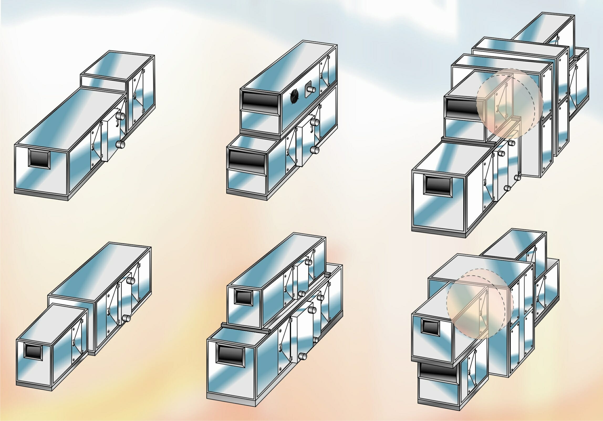
- Configuration: horizontal, vertical, double (or triple) decked, special to accommodate heat recovery devices, piping or control panels (some examples are given in Fig.1).
- Position of components in direction of air flow to achieve performance, e.g. dehumidification plus reheat.
- Number of unit sections for transportation and installation.
- Provisions for access for maintenance and component replacement.
- Requirements for safety: drive guards, fan inlet/outlet guards, safety grillage, lights, electrical isolation, earthing/bonding, arrangement of door handles / hinges, locks, retaining stays (safety and security), warning / information labels.
- Baseframe design and height (e.g. to accommodate drainage traps).
COMPONENTS
The air handling unit incorporates a variety of components to condition and control the air passing through it:
- Air movement (fans)
- Air cleanliness (filters)
- Air mixing/control (dampers)
- Temperature changes (air heaters/coolers)
- Moisture content changes (humidifiers / dehumidifiers)
- Energy recovery (thermal wheels/recuperators/reclaim coils)
- Noise control (attenuators).
The particular components and their relative positions in a given unit depend on system design, the particular application, and the changes in the psychrometric condition of the air to be achieved under varying conditions of load or modes of operation.
Selection Parameters
The basis of component selection may be governed by the specifier’s maximum allowable face velocity or pressure drop requirements, or may be based on the manufacturer’s experience and recommendations. The following values are typical:
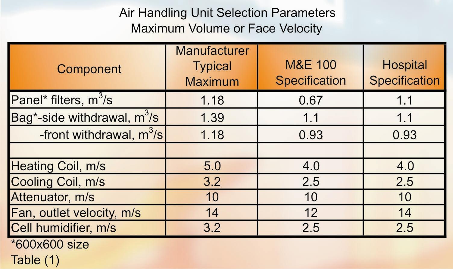
Fans & Motors
The type of fan used in air handling units is usually the DIDW (double-inlet, double-width) centrifugal type, though the high performance axial-type may be employed for certain applications. The use of plug fans may show economic benefits in certain circumstances. Centrifugal fan impellers are normally of either the forward-curved multiblade type, typically 36 to 48 blades, and used for a FTP (fan total pressure) requirement up to around 750 Pa, or of the backward-curved-blade type, typically 8-12 blades for a FTP up to 2500 Pa. The total efficiency of the forward-curved type is typically 60-65%, that of the backward-curved 75-85%.
Fan speeds typically range from 300 to 3500 rev/min according to fan type, air volume flow rate and FTP requirements. Motors range from fractional kW size to over 100 kW. Fan sound power levels range from 70 dB (ref 10-12 W) for very small fans up to 100-110 dB for fans used in high volume, high FTP applications.
Fan selection involves choosing the most inexpensive combination of size, arrangement and type and class of construction to meet the required duty, while providing stable operation at acceptable sound level, efficiency and power consumption. This is normally accomplished by using a computer program to present a range of alternatives and then print an operating characteristic. Fan selection involves consideration of fan type, impeller type, fan size and speed, outlet velocity, absorbed power, efficiency, construction and sound power level, which must be considered in conjunction with the following:
- Air volume flow rate, m3/s
- Fan static pressure FSP, Pa (resistance of system external to unit, and unit itself)
- FTP, Pa = FSP+ FVP (fan velocity pressure due to outlet velocity)
- Entering air condition: temperature, degC; humidity % rh; density kg/m3
- Condition of air surrounding unit (may affect motor selection, if external)
- Altitude/barometric pressure at plant location (effect on air density)
- Type of application or service: mechanical strength of impeller, shaft, bearings and casing (according to FTP and fan speed)
- Type of system and possible changes in duty requirements, e.g. volume and pressure changes in a variable volume system
- Space available for motor and drive (if external to unit)
- Fan arrangement, position of outlet, direction of discharge, position of duct connection
- Type of drive (indirect using pulleys, direct using couplings), and arrangement-drive adjustments, provision of standby motors,
- Accessories; scroll access doors, drain plugs, type of bearings, drive guards, vibration isolators, flexible connections, inlet guide vanes
- Special features such as spark-proof construction or protective paints or finishes
- Motor requirements: type, output, frame size, enclosure, bearings, electrical supply, insulation rating, torque, starting/running currents, run-up time (of large fans), efficiency and power factor (full and part load), drive type and adjustment, mounting, vibration isolation, cable connections, thermistor protection
- Starter/inverter requirements: type, rating, enclosure, isolation, fusing/ protective devices, indicating and interlocking requirements, speed control
- Fan sound power level: octave band spectrum, required in-duct/space levels, attenuator requirements (pressure drop, space and cost).
Air Filters
Most air handling units employ standard (600 x 600) or half-size filters (600 x 300) from well-known manufacturers. Filters are generally specified by type, method of renewal, and efficiency. Commonly in use are panel, bag and compact type, which are replaced when a predetermined dust loading (pressure drop is reached). Washable, oil-wetted or automatic filters are very rarely used in air handling units. Panel type filters for pre-filtering duty are typically EU3 or EU4 (Eurovent Grade) and operate to about 150-170 Pa final (dirty) resistance. Bag or compact filters used as secondary or main filters usually range in grade for commercial/light industrial applications from EU5 (250 Pa dirty), through EU6 & EU7 (300 Pa) to EU8 (350 Pa).
Special applications such as hospital operating theatres, pharmaceutical manufacture or clean rooms generally use a higher grade of special filter of which there are numerous types, usually termed HEPA (high efficiency particulate air) filters. Many of these are close to 99% efficiency; but 99%+ types are also available. The design and effectiveness of filter frames and gaskets is extremely important for HEPA grade filters.
A separate class of filter is available for the adsorption of odours (usually atmospheric) to protect, for example, the contents of art galleries, museums or libraries. These are activated carbon type of which a number of formulations are available to cater for various contaminants, particularly SO2. A typical specification (M&E TR70) requires 80 kg of activated carbon per 1.0 m3/s of recirculated air to be treated and 120 kg per 1.0 m3/s when treating fresh air. Dwell (contact) times between air and carbon are specified as 0.2 seconds and 0.3 seconds respectively, and maximum air resistance as 100 Pa. The carbon filter requires upstream protection by a filter of at least EU5 grade. In an important application (protecting national treasures) then the upstream filter would be EU7 and an after (tertiary) filter of EU7 would also be provided.
Filter selection requires consideration of the following:
- Air volume flow rate, m3/s, to be handled. (If this is variable, arrangements may be necessary to prevent pockets on bag filters collapsing at low air flow).
- Condition of air to be filtered: temperature, humidity, dust loading/contaminants.
- Filter efficiency/arrestance, dust holding capacity, EU grade, HEPA type, etc..
- Initial (clean) and final (dirty) air pressure drops, Pa.
- Filter duty, e.g. pre-filter, secondary or after-filter.
- Resistance of filter, filter frames, casings and cell-holding frames, gaskets and fixing/securing devices to temperature and moisture: also fire properties (normally fireproof or self-extinguishing), resistance to frame/edge air leakage.
- Means of filter replacement: side/front withdrawal (or other), access doors/ hatches, lights.
- Instrumentation: filter pressure drop manometers, gauges, pressure switches, sensors.
Air Control Dampers
Dampers in air handling units may be used for the control of air temperature, flow or pressure, or for air mixing. There are two basic types of multi-leaf air control damper: the opposed- bladed and the parallel-bladed and their control characteristics are different. The relationship between the air volume flow rate passing through a control damper, the angular opening of its blades, and the change in air pressure drop depends on the control authority of the damper. For shut-off applications, dampers should be opposed-blade type. For mixing and bypass applications, dampers should be parallel-bladed. Aerofoil-section blades are to be preferred.
Exhaust discharge dampers in mixing/diverting box applications should be opposed-blade. Return/recirculation air dampers in mixing boxes may require the addition of a resistance grid to achieve the correct pressure drop relationship to fresh/exhaust air circuits. Dampers fitted to the unit at duct connection locations may be fitted externally or internally to the unit casework. For units located outdoors, dampers should be internal type.
Selecting a damper requires consideration of the following factors:
- Air volume flow rate, m3/s
- Function of damper: shut-off, bypass, mixing, diverting, etc.
- System resistance, damper size and resistance and authority.
- Pressures at point of operation and allowable air leakage (through the blade seals and via the blade shaft bearings).
- Height/width ratio, number/depth of blades, frame, frame seals, blade seals, operating mechanism, materials/finish, operating torque and holding torque when closed.
- Where air conditions are contaminated, eg swimming pools, dampers may have epoxy protection applied.
- Actuator/motor type, spring-return provision.
Heating & Cooling Coils
Fluid coils (water, steam, refrigerant and glycols) are of the finned-tube type, except frost coils may be bare-tube type. For heating duty, coils are typically of 5/8 inch (16 mm) outside diameter copper tube with continuous plate-type aluminium fins of 0.15 mm thickness (0.4 for M&E 100), spaced at from 4 to 12 fpi (fins per inch) (6mm – 2mm fin spacing). For sensible cooling duty, fins may be 0.1 thicknesses, of aluminium; where cooling is accompanied by dehumidification then fins may be aluminium, copper (0.25 M&E 100), electro-tinned copper or plastic-coated aluminium. Hot water heating coils are typically 1 or 2 rows deep; 2mm fin spacing, 30 Pa air pressure drop, 15 kPa hydraulic resistance. Chilled water coils are typically 6-8 rows deep, 2.5mm fin spacing, 120 Pa air pressure drop, 20-35 kPa hydraulic resistance. To maximise on fin-block (heat transfer) area, cooling coils in particular may have external headers located in header boxes on the outside of the air handling unit casework. Electric heater batteries, using enclosed tubular elements, may be used for smaller heating loads, typically up to about 30 kW.
Coil selection considerations include:
- Air volume flow rate, m3/s
- Entering and required leaving air conditions.
- Heating/cooling medium available, flow/return temperatures and pressure.
- Materials of construction; tubes, fins, headers, casing.
- Fin block area, number of rows, fin spacing, division of coil for control.
- Air velocity m/s, air-side pressure drop Pa, hydraulic resistance kPa.
- For dehumidifying coils: quantity of moisture removed, prevention of carryover, use of eliminators and material, construction of drain pans and material, drain positions, trap design (to avoid legionella).
- Piping connections: location (should be counterflow), number, size, type, provision for isolation, draining, venting, coil removal, insulation.
Humidifiers
Recirculating water-spray type humidifiers are generally not used because of potential maintenance problems and risk of legionella. The choice is typically between atomising spray type (non-recirculating), direct-steam injection using a jacketed manifold, electric steam generator and, ultrasonic type. Of crucial importance to the success of humidifier operation is the way in which it is mounted into the air handling unit. Correct positioning of the humidifier to achieve thorough mixing of air and evaporated moisture without carryover or condensation onto the inner walls of the humidifier chamber or downstream components is essential.
Selection considerations include:
- Air volume flow rate, m3/s
- Entering air volume, velocity, velocity profile, dry bulb temperature degC, and percentage saturation (% SAT).
- Required moisture addition kg/h and leaving conditions necessary to achieve this.
- Unobstructed length downstream of humidifier, typically 1 m minimum required.
- Method of humidifying: electrical power, steam (pressure) and water consumption (water quality, pressure, any special requirement, e.g., demineralised).
- Control and safety requirements.
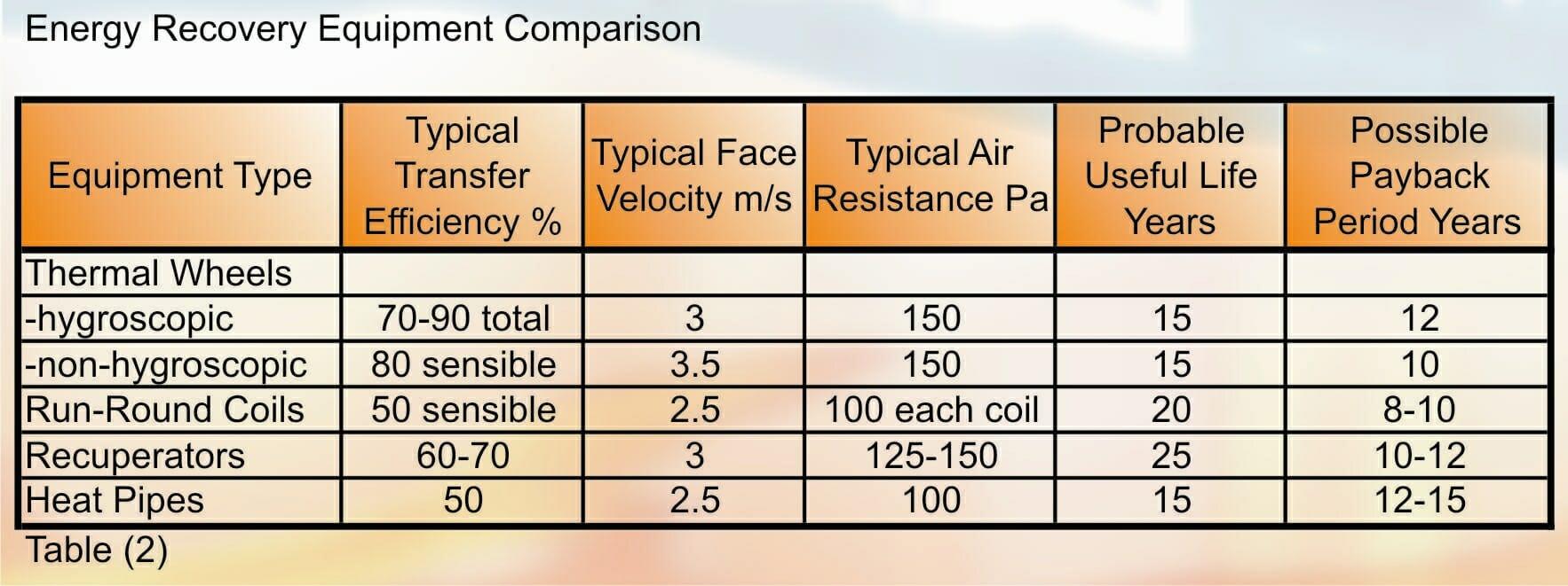
Energy Recovery Equipment
There are four main types: thermal wheels, run-round coils, recuperators and heat pipes:
- Thermal wheels (or rotary heat exchangers) comprise a wheel or drum containing a corrugated material. This is slowly rotated between a fresh or supply airstream and an exhaust airstream. Heat is absorbed from the warmer stream and transferred to the cooler. Two types of infill material are available -hygroscopic (retaining moisture, and capable of transferring both sensible and latent heat) and non-hygroscopic (transferring sensible heat only). Advantages are high efficiencies and the ability to transfer total heat. Disadvantages include a high space requirement and the necessity for the two air streams to be adjacent, usually accomplished using by using a double-deck air handling unit.
- Run-Round Coils are finned water-tube coils located in supply and exhaust air streams and interconnected by a pumped water (or glycol) pipe work circulating system. This system is seasonally reversible, providing preheating in winter and pre-cooling in summer. The two or more coils can be completely separated and located in individual air handling units.
- Static Recuperators (or air-to-air plate heat exchangers) transfer air from one airstream to another by indirect contact on either side of a metal heat transfer surface -a series of closely spaced parallel plates, usually aluminium. Other metals and protective coatings are available where the airstream is contaminated or corrosive. Recuperators require the air streams to be adjacent and this is usually achieved by using a double-deck air handling unit. A bypass damper system may be used for control purposes.
Heat Pipes are passive heat exchangers that make use of a closed fluid cycle within an arrangement of sealed vertical or horizontal tubes. When cold air passes over one end of the tubes, the fluid within condenses and heats that air. Warmer air in an adjacent airstream passing over the other end of the tubes is cooled as it evaporates the fluid within the tubes. The action is reversible and operates whenever there is a temperature difference between the ends of the tubes. Application is restricted to specialised projects.
A comparison of the energy recovery equipment types follows:
Attenuators
Air handling unit manufacturers normally offer a range of cased attenuators, matched to unit cross-section dimensions and construction/finish. A typical range employs from 2 to 8 vertical splitters (according to unit width) contained in modular length sections from 640 to 2720 mm, with a wide range of performance. Attenuator designs may be customised to meet specific acoustic criteria.
| EXAMPLES OF AIR HANDLING UNIT ATTENUATOR INSERTION LOSS dB | ||||||||
| Frequency Hz | ||||||||
| Section Length (mm) | 63 | 125 | 250 | 500 | 1k | 2k | 4k | 8k |
| 640 | 3 | 5 | 11 | 22 | 28 | 23 | 16 | 11 |
| 1600 | 5 | 12 | 28 | 42 | 49 | 48 | 33 | 21 |
| 2720 | 8 | 19 | 44 | 50 | 50 | 50 | 49 | 29 |
Attenuators should not be fitted directly at fan discharge. A properly designed fan diffuser section with a perforated baffle plate is required to spread the air between the attenuator splitters and achieve rated acoustic performance at design pressure drop. The length of a proper diffuser section increases with unit size/cross-section, typically ranging from 480 to 1280 mm long.
