 Cassette Split Systems
 Safety Gloves
 UV Leak Detection
 Condensate Drain Pipe
 Nitrogen Regulators
 Filter Driers
 Filter Cores for Core Shells
MASTERCLASS – AIR CONDITIONING TECHNOLOGY
Vol 40 – Air Handling Units Part 1
In last month’s article we completed our review of Ducted System Design.
This month we commence a detailed review of Air Handling Units. Part 1 looks at the design, specification, selection, performance and application of air handling units. The concept of modularity and its benefits are explained. The construction and specification options of the casework, or enclosure system, are also examined.
THE AIR HANDLING UNIT
An air handling unit consists of one or more factory fabricated assemblies designed to provide the function of air moving with a choice of facilities as required to achieve air mixing, air volume control, filtration, heating, humidifying, cooling, dehumidifying, space pressurisation, energy recovery and noise/vibration control. Special units may provide accommodation to house related services or equipment such as piping, starters or inverters, and control panels.
Air handling units are available in a wide range of sizes, capacities and configurations according to the air volume flow rate to be handled. Typically, standard units cover from 0.05 to around 25 m3/s, while special units may range up to 50 m3/s. Units are available to cater for a wide range of air-side system resistances: for low pressure (up to 500 Pa), medium pressure (up to 1000 Pa) or for high pressure (up to 2000 Pa), though units for working pressures of 3000 Pa have been constructed. Unit configurations include horizontal, double-deck, L-shaped, vertical (upward airflow) and vertical (downward airflow).
The selection of air handling equipment involves consideration of a wide variety of technical and cost factors. Technical factors relate to system design and unit specification/performance, building and space requirements, service connections, installation, commissioning, operation and maintenance. Cost factors include the capital cost of the air handling unit plus the costs of installation, related structural/building requirements, ductwork, pipework and electrical connections. Also important may be energy costs (at both full and part-load), operating costs, availability of spares and service, maintenance skills and component reliability/life. A detailed analysis may require life-cycle costing techniques and quality/value engineering judgements.
The establishment of air handling unit specification requirements and performance criteria involves consideration of casework, components, accessories and special features.
MODULARITY
The design of air handling unit casework is typically based on a standard modular dimension chosen by a particular manufacturer. The starting point may be the development of a range of cross-section sizes which relate to standard filter sizes, nominally 600 x 600 mm square and 600 x 300 mm for a half-size panel or cell. Thus, with suitable allowances for filter frame, a standard module size might be 320 mm. A typical unit range (as Fig.1) might start as 3 modules wide x 3 modules high and extend to 9 x 9.
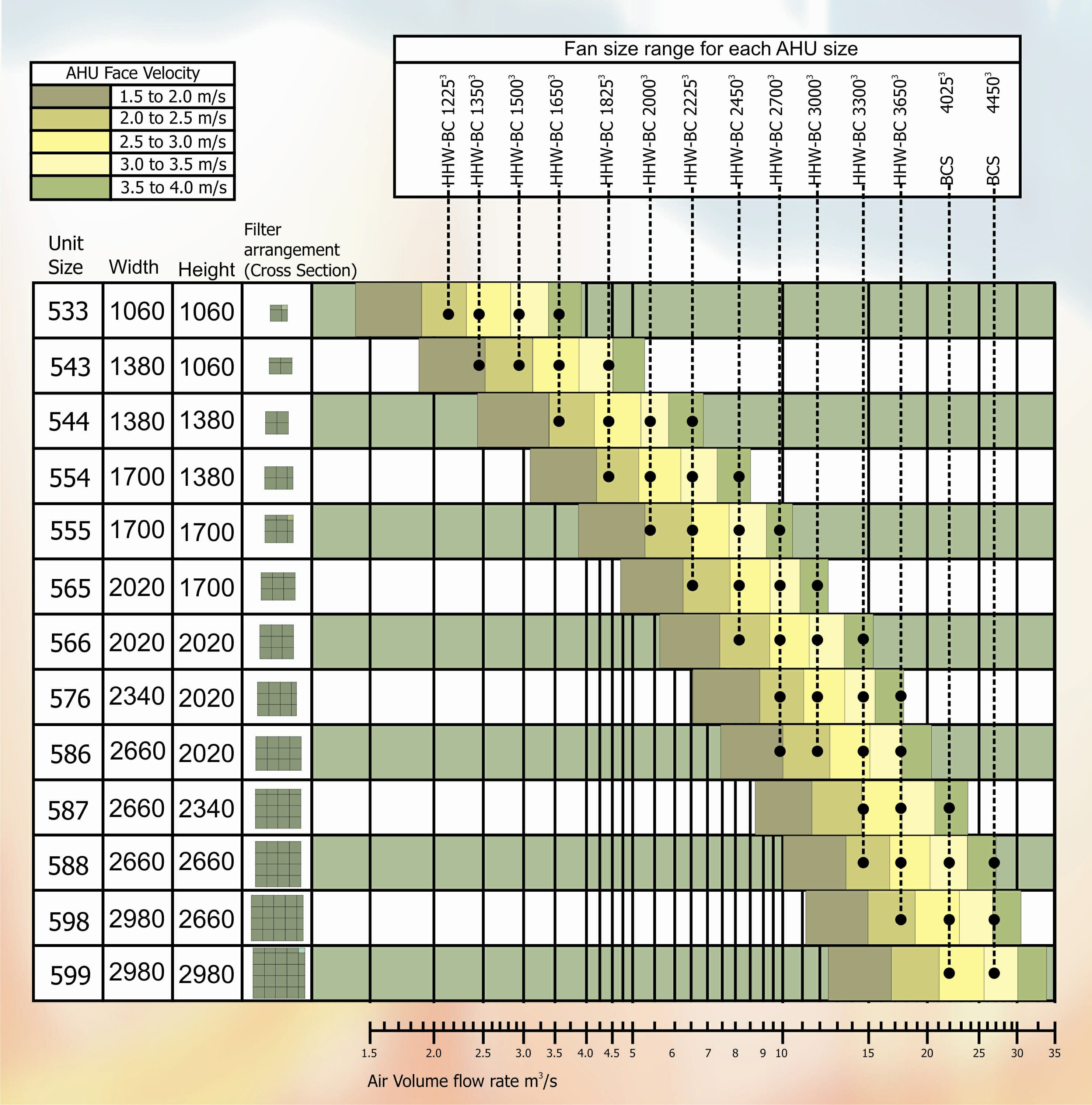
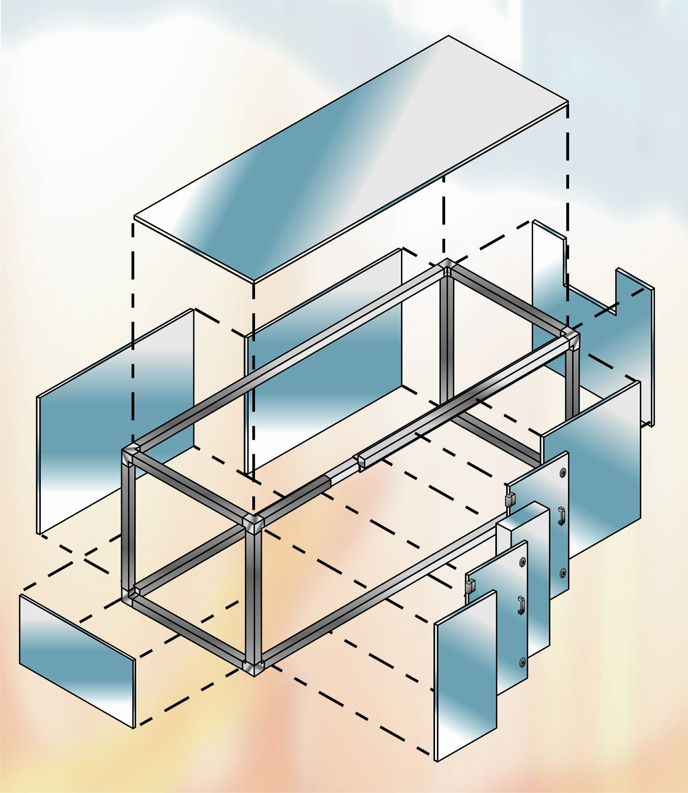
A typical unit utilises a casework (Fig.2) constructed from a system of framework (corner joints and profiled connecting members) with modular infill panels. With a frame size of 50 mm, the cross-section overall sizes of the unit are (2 x frame)+(n x 320), where n is the number of modules. Thus (in Fig.1), a 3 x 3 unit is (2 x 50)+(3 x 320) = 1060 x 1060. Similarly, an 8 x 6 = 2660 x 2020.
The length of an air handling unit may be developed on a similar modular basis, according to the components employed but, for economy in unit length and cost, a half-module is typically introduced. Hence, modular lengths may be 160, 320, 480, 640, 800, 960, 1120 & 1280. For some standard components, unit length is basically independent of unit size. For example:
TABLE 1
| Panel filters, side withdrawal | 480 | |
| Panel filters, front withdrawal | 640 typically | |
| Bag filters, side withdrawal | ||
| bag length max | 380 | 480 |
| 600 | 640 | |
| 725 | 800 | |
| 900 | 1120 | |
| Front withdrawal | +640 typically for access | |
| Heating coil, 1 – 3 rows | 320 | |
| Heating coil, 4 – 8 rows | 480 | |
| Cooling coil, 1-8 rows | (sensible cooling) | 480 |
| Cooling coil with eliminator | ||
| 1 – 3 rows | 480 | |
| 4 – 7 rows | 640 | |
| 8+ rows | 960 | |
Each time a section frame is introduced, the length of a particular section will increase by 2 frame sizes, eg. 2 x 50 frame = 100. Thus, a 6 row heating coil section would be 480 + 100 = 580 long. However, in practice, it is possible to combine components in common sections up to about 3.8 m long (depending on weight and site access) to economise on total unit length.
Some component lengths, e.g. fans, mixing boxes, are dependent on unit size and performance duties; others, e.g. attenuator length, are performance related. For the larger units, lengths of individual sections may also range up to about 3.8 m long.
The concept of modularity in air handling unit design is extremely important. It allows the manufacturer to satisfy the particular requirements of a system design/installer using a standardised “building-block” approach. This simplifies design and selection, minimises costs, speeds delivery and guarantees specification and performance. Where, for no good reason, a specifier introduces non-standard specification, dimensional or performance requirements, this inevitably attracts a cost premium, and possibly a performance risk.
CASEWORK
The casework of an air handling unit, which houses the various operating components, has to satisfy a number of important requirements:
- Mechanical strength.
- Deflection.
- Operating pressure.
- Air leakage standards.
- Thermal resistance
- Condensation prevention
- Corrosion resistance
- Sound reduction
- Fire-resistance
- Hygienic and aesthetic considerations
- Demountability
- Access to components
- Service connections and penetrations
- A supporting baseframe.
Mechanical Strength
The casework must be mechanically strong and adequate to bear the weight of internal components. A casework panel should not deflect more than 120th of its span. The unit floor and roof should cater for the weight of installation/maintenance personnel. The casework must also satisfactorily withstand the temporary added stresses of loading, transportation, hoisting and moving into position at site (which must be carried out in accordance with the manufacturer’s recommendations).
Casework will deform under abnormal operating conditions, e.g. a fire damper closing. Suitable controls should be employed to limit abnormal conditions, e.g. a fan should not be able to start against a system of closed dampers as the resultant pressure rise may damage internal bulkheads or the casework itself. In high pressure situations, high pressure limit switches should be fitted to initiate fan shutdown.
A standard unit of 2 x 2 m cross-section may be satisfactory for a temporary pressure condition up to 2500 Pa; above this size the allowable pressure progressively reduces (to about 2000 Pa) as unit cross-sectional area increases. Under these conditions, while the panels will deflect, they will return to their normal position when the over-pressure is removed. Excessive over-pressures may cause permanent damage.
Air Leakage & Pressure Classification
The casework is normally designed to satisfy the maximum operating pressure of the fan or system plus an appropriate safety margin. This margin should take into account any pressure variations which may take place under normal operating conditions, e.g. volume changes, dirty filters, etc. Units may be rated for air leakage/pressure classification according to the HVCA Ductwork Specifications DW/142 & /143, typically:
TABLE 2
| AIR LEAKAGE STANDARDS FOR AIR HANDLING UNITS | ||
| CLASS | Static pressure differential Pa | Maximum allowable leakage
litre/sec per m2 surface area |
| A | 500 | 1.53 low pressure |
| B | 1000 | 0.80 medium pressure |
| C | 2000 | 0.42 high pressure |
| D | 2500 | 0.16 high pressure |
It is important to avoid over-specifying the pressure/air leakage requirements. Class A & B are readily met by standard forms of construction. Class C requires extra internal seals and trim and may involve an additional cost of some 5%. Class D may be particularly onerous and attract additional costs in the range 10-20%. It should be borne in mind that an air handling unit is usually a small part of the total surface area of the air distribution system and that ductwork is not usually full of access doors and service penetrations. The pressure class should be specified accordingly. On a practical note, a unit tested or operating under negative pressure will normally leak less than under positive pressure (as panels and doors are drawn inwards and tight onto their frames or gaskets). Also, a small unit may leak relatively more than a large unit, due to the unfavourable ratio of panel and door perimeter length to total surface area.
Panel Construction
This depends on mechanical strength, thermal and acoustic requirements, surface finish and, of course, cost and ease of manufacture. Double skin construction using outer and inner skins of galvanised steel sheet with an insulation infill is a typical industry standard. Where the unit is located externally or handling air with a large inside/outside temperature difference across the panel with a risk of condensation on the cold surface, then a coldbridge-free form of panel construction may be employed. A comparison of double skin and coldbridge-free construction (Fig.3) shows how the latter may employ additional gasketting to avoid metal-to-metal contact between inner and outer skins. Only sections subject to condensation need to be constructed with a coldbridge free panel and frame system.
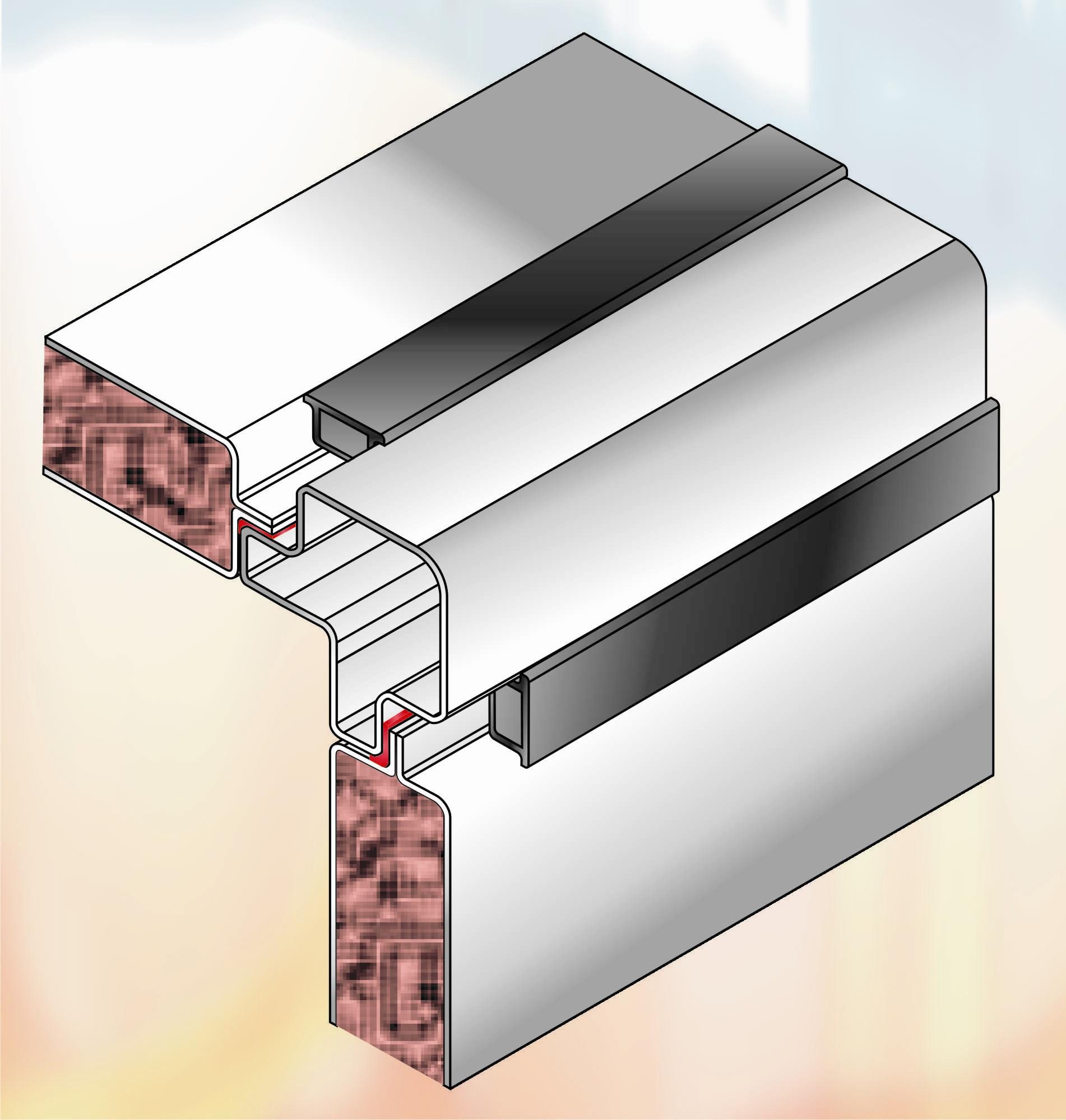
A typical standard double-skin panel is manufactured to be of 40 or 50 mm overall thickness (small units, up to say 4 m3/s, may use 25 mm panels). A proprietary form of coldbridge-free panel, as illustrated, is available in thicknesses of 45 and 30 mm. Metal skin thickness of 1.0 mm is typical for both inner and outer panel sheets. A standard insulation infill is glass fibre having a thermal conductivity k = 0.035 W/mK and a density of 25-30 kg/m3. Increased metal thickness with insulation of lower thermal conductivity and higher density may be employed where specific thermal or acoustic criteria have to be met. For example, mineral wool thermal insulation infill of medium (60 kg/m3) or high density (80 kg/m3) may be employed. Conductivity may be reduced using a blown foam (k=0.02-0.025 W/mK). Typical thermal resistance of various panels is:
TABLE 3
| THERMAL RESISTANCE OF AHU PANELS, R = m2K/W* | ||||
| DOUBLE SKIN | COLDBRIDGE-FREE | |||
| Panel thickness, mm | 25 | 40 | 30 | 45 |
| Insulation density, kg/m3 | ||||
| 25 (low) | 0.74 | 1.12 | 0.82 | 1.26 |
| 60 (medium) | 0.80 | 1.20 | 0.87 | 1.34 |
| 80 (high) | 0.83 | 1.25 | 0.92 | 1.41 |
(* Note that thermal resistance excludes the effect of inner and outer surface film resistances, and that thermal conductance, C = 1/R, W/m2K).
Computer programs or psychrometric/temperature gradient calculations may be used to establish suitable panel thicknesses, insulation densities and where use of coldbridge-free construction is appropriate to prevent or limit risk of condensation on cold surfaces.
The other determining factor in panel construction is noise breakout. The SRI (Sound Reduction Index) of a particular form of panel construction may be determined by testing in an acoustical laboratory to a recognised standard. Generally, SRI performance follows the mass law, the heavier the panel the better its performance. The thickness (mass) of the panel sheets largely determines test performance. (In practice, the frame construction and seating of panels within it is also important). Thicker gauges of metal sheet improve acoustic performance at the lower frequencies. For special situations, triple-skin construction may be employed, particularly on fan-section casework. Some examples of panel acoustic performance are:
INSERT TABLE 4
Casework Finishes
A number of options are available depending on cost considerations, unit application and location, and potential risks of moisture or other damage, corrosion or deterioration. Generally, panels (and casework) should be smooth and readily cleanable, providing a hygienic interior surface finish. Panels can be galvanised sheet steel, plain or painted. For very special applications, aluminium or stainless steel panels (possibly for the internals of certain sections only) may be used. A number of manufacturers use a plastic-coated metal sheet. GRP (glassfibre reinforced plastic) casings and water tanks may be used for spray or cell humidifiers. Possibly, the only way to fully protect all steel cut-edges and holes, and the ledges and crevices in panelwork, casings and trim is to fully fabricate all panel materials and then treat with a corrosion-resistant finish before assembly and fitting into the unit. This may be accomplished by the use of appropriate surface treatments and the application of a cathodic electrocoat paint finish (similar to that used for car bodies).
Where, for architectural reasons or for identification, a particular external colour is specified, and then the electrocoat may be factory overspray painted.
NEXT MONTH: Vol 41 – Air Handling Units, Part 2
DISCLAIMER: Whilst every effort is made to ensure absolute accuracy, Business Edge Ltd. will not accept any responsibility or liability for direct or indirect losses arising from the use of the data contained in this series of articles.
