 Cassette Split Systems
 Safety Gloves
 UV Leak Detection
 Condensate Drain Pipe
 Nitrogen Regulators
 Filter Driers
 Filter Cores for Core Shells
MASTERCLASS – AIR CONDITIONING TECHNOLOGY
Vol 26 – Low Ambient Control for Single and Multiple Fan Condensers on Air Cooled Systems
We now continue our study of the various means of providing Low Ambient Control for single and multiple fan condensers on air cooled systems.
One Fan – Single Phase – Air Cooled Systems
Low Ambient Control of single fan air cooled systems is best achieved by the application of variable airflow by means of variable fan speed control. In addition to maintaining the desired head pressure, the condenser fan speed control also assures minimum fan noise under all operating conditions. Since the condenser fan speed and resultant airflow will only be that required to maintain adequate head pressure, the fan will operate at lower speeds resulting in reduced noise, especially under low ambient conditions.
As it is the high side system pressure that we wish to maintain at a suitable level during cold external conditions, the ideal property to directly measure for control is the high side pressure. This can be achieved by use of a pressure transducer which reads pressure and converts this to a measurable electrical signal (0 – 10V or 4 – 20mA are common). Pressure Transducers have reduced in price substantially over the last ten years but are still considered too expensive by most manufacturers for small systems.
Pic 1…
The use of a low cost temperature sensor positioned on the liquid line leaving the condenser coil is therefore usually used. This does however result in the sensor reading a sub-cooled liquid temperature rather than the condensing temperature. Moreover, there are delays between in a change to fan speed / airflow / high side pressure and the change in temperature reading at the liquid line due to system thermal inertia since the liquid in the base of the condenser must make it’s way to the sensor. This response time will also vary if the system is incorrectly charged.
The control algorithm in the software of the electronic controller must be carefully written to control the fan correctly or serious hunting of the fan will occur.
It is also possible to consider positioning of the temperature sensor on the bends of the condenser coil. This can be achieved by brazing a small tubular pocket, in which the temperature sensor is located to one or more bends of the coil. This has the advantage of reading a coil temperature that can almost be directly related to the saturation temperature (condensing temperature) of the refrigerant in the coil. Positioning of the sensor is very important to ensure that it does not read super-heated vapour in the upper region of the coil or sub-cooled liquid at the base. Theoretically, the majority of the condenser coil surface should contain saturated vapour in the process of converting to saturated liquid at a common temperature and a stable control should therefore be attainable. Changes in the amount of charge in the condenser, the circuiting of the condenser coil (which may also have to serve as an evaporator in heat pump applications), and other parameters can result in unstable operation and some manufacturers therefore avoid this approach.
Heat transfer paste should be used around the temperature sensor to ensure close agreement in pipework temperature and the surface of the sensor. The sensor must be located at the point recommended by the manufacturer.
Hard Start
In low ambient conditions, the motors can become very cold, particularly during the night if the system has been shut down. This causes contraction of various materials within the motor to occur at different rates which can lead to increased resistance to starting the motor. The lubricants within the bearings can also experience considerable increase in viscosity, thereby increasing the required starting torque.
The condensing unit may be positioned where a prevailing wind cause the condenser fan and motor to free-wheel in the opposite direction to normal running (wind-milling).
The low ambient controller will at this time be sensing a low temperature and would therefore attempt to start the fan at low rpm. The resistance imposed by any of the above, might prevent the fan form starting at all, leading to potential motor damage or tripping of the motor overload. The software routines in the low ambient control elements of the controller should cater for this and this is incorporated in the controllers illustrated in Figures 1 & 2 above.
One Fan – Three Phase – Air Cooled Systems
When it comes to larger systems, the increased airflow demands use of 3 phase motors. Low ambient control principles are applied in exactly the same way as for single phase motors with the following exceptions:
a) The low ambient control electronics are much more complex as three phases are now being controlled.
b) The relative cost of a pressure transducer is less prohibitive thus allowing this to be used for direct measurement of the high pressure which is after all the primary parameter to be controlled.
One Fan – Damper Controlled Systems – Air Cooled Systems
Many air cooled systems embody a centrifugal condenser fan which is capable of generating much higher external static pressures than axial flow fans. This has the advantages of being able to site the equipment indoors and duct the supply/discharge air from/to the outside. Where noise levels are critical, the centrifugal fan also has the ability to overcome the resistance imposed by sound attenuators.
With this type of fan it is possible to use a set of modulating dampers to throttle the airflow over the condenser coil in order to maintain high side pressures at the correct level. This ensures correct delivery of liquid refrigerant at all times to the TEV and avoids liquid flashing due to inadequate pressure. Evaporator saturation temperature and pressure are also maintained. The fan is allowed to run at full speed continuously. This arrangement is however rather wasteful of energy. Having said this, it must of course be remembered that Low Ambient Control in itself causes an enormous waste of energy by forcing systems to run at artificially high discharge pressures all year round. There are better ways of running systems but these involve higher capital cost.
The damper blades are connected to a linkage which is operated by an hydraulic ram. The ram contains a spring which is arranged to continually attempt to close the damper blades. If the compressor is not running, the high/low side pressures equalise, and the dampers close. The connection arrangement is shown in Figure 1.
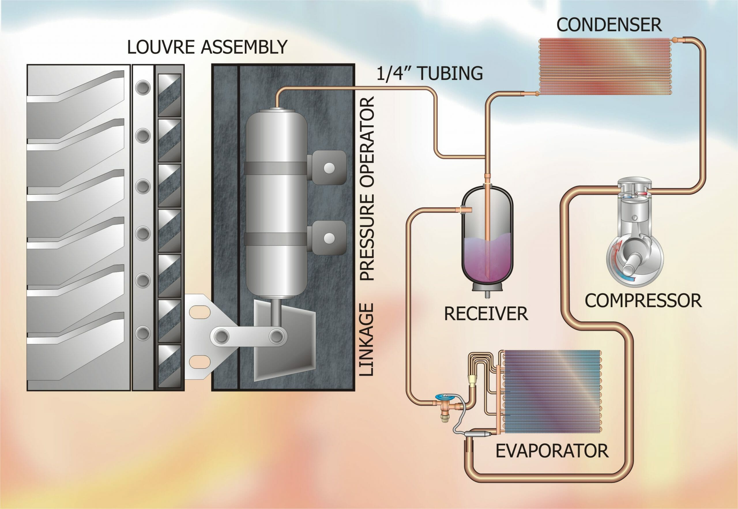
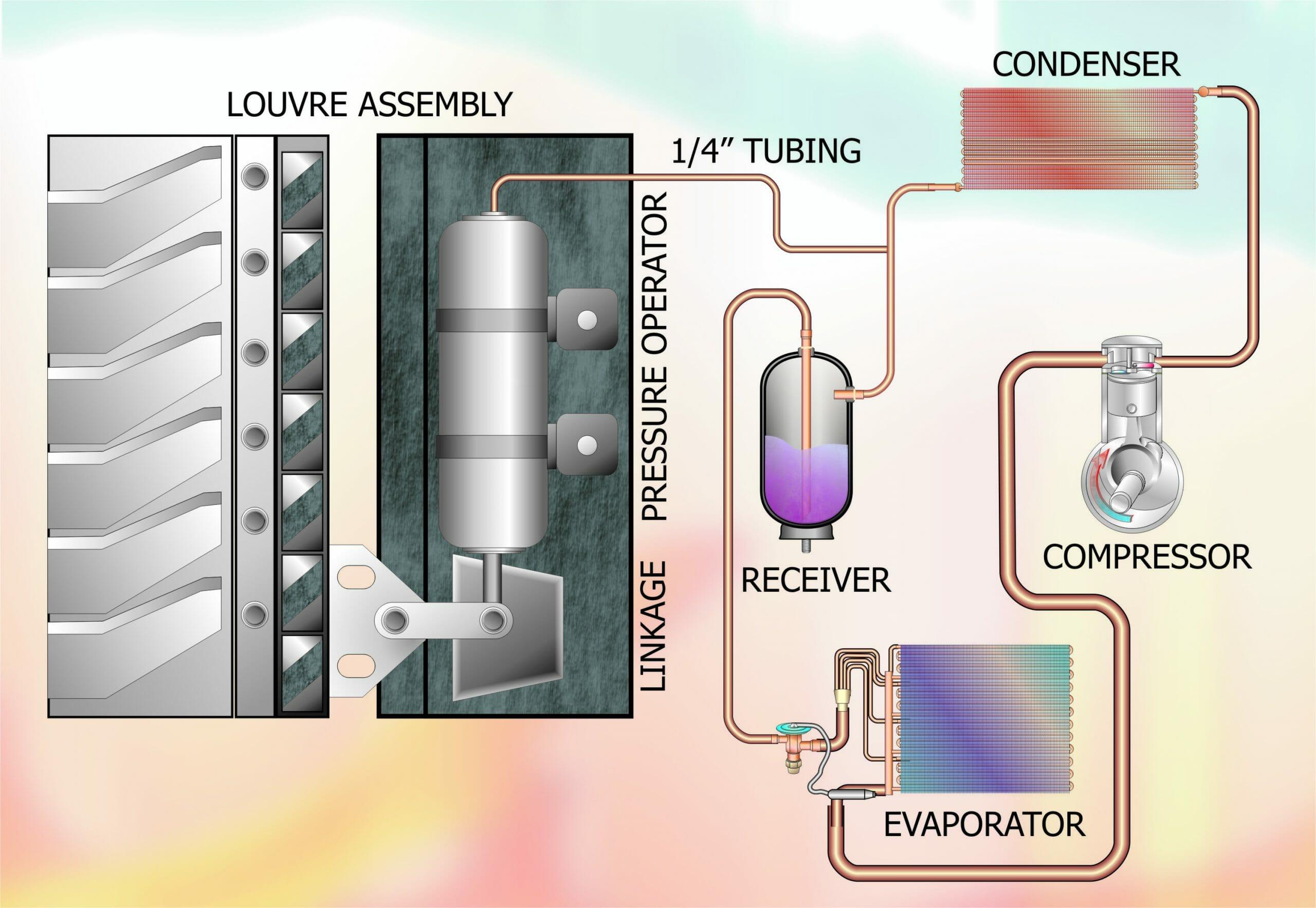
Figure 1
When the system starts, the high side pressure starts to rise. Whilst the fan is running at full speed, there is no airflow over the condenser coil. The high side pressure continues to rise rapidly and ultimately reaches a point where it is able to overcome the resistance of the spring. As the pressure increases, the dampers progressively open until a balance is reached between high side and spring pressure and at the desired high side pressure.
If the ambient temperature rises, the high side condensing temperature increases and causes the dampers to open further until the condensing temperature and high side pressure are restored to the former level. The reverse occurs when ambient temperature falls. This arrange allows operation down to very low, sub-zero ambient temperatures and is also very effective in minimising nuisance tripping of the LP Switch (described in an earlier article).
This form of pressure operator is a trouble free bellows, normally designed to withstand up to 30 bar (450 PSI) maximum operating pressure and is configured in order to provide a uniform response to pressure changes. These pressure changes are converted into shaft movements of up to 50 mm. One of the major manufacturers of this type of operator is Robertshaw U.S.A. and these units can be applied to both air conditioning and commercial refrigeration systems. The key features of this type of device are:
- Elimination of costly wiring, electric motors, pressure switches and connection to same.
- Continuous and infinite modulation of damper blades and air flow to maintain compressor high side pressure.
- A heat treated berilium copper bellows construction contained in a hermetically sealed case eliminates the need for seals or gaskets which otherwise might leak.
- The manufacture assembly is factory lubricated and requires no further servicing.
The Robertshaw Model PO 20 (50mm nominal travel) should be mounted so as to obtain half of this travel before top dead centre and half of this travel after top dead centre. To obtain this, a lever arm 1.410 long should be used.
Using the previous method of calculating, the torque outputs as summarised in the following table are found.
PO 11 PO 20
Nominal Travel 1″ 2″
Effective Area 0.36 sq.in. 0.90 sq.in.
Lever Arm Torque (per 10 PSI) 0.660 lb.ft 1.140 lb.ft
Midpoint 2.38 in. lbs 12.7 in. lbs
Start and End 1.68 in. lbs 8.9 in. lbs
Nominal 2.00 in. lbs 10.5 in. lbs
These torque values are for a 10 psi change in pressure. A 20 psi change will double these values and a 30 psi change will triple these values, etc.
Linkage arrangement on dampers should be provided to establish the length as previously described for the amount of rotation required to provide full open to full closed positions of the blade.
Dampers should be as nearly friction-free as possible and normally as balanced as possible when subjected to the fan loading. Small amounts of frictional drag, such as produced by loose fitting nylon or Oilite bearings and normal linkage which does not bind, is not objectionable. Generally, there is sufficient vibration caused by the running fan to eliminate the frictional effect and cause it instead to act as a snubber to prevent hunting. A good installation in operation might require up to 5 seconds to return to any normal pressure position after being forced out of that position manually.
Successful applications have been achieved with dampers which are unbalanced either by their own centre of gravity or by the fan loading on the blades. It is recommended that the field Application Engineer not attempt such an application unless he/she is fully familiar with mathematics of the entire damper operator system.
Airflow Control
It must also be remembered that air restriction through dampers is not linear with blade rotation. Curves illustrating the relationship between the temperature of the refrigerant versus the pressure of the refrigerant plus the temperature-pressure operating range of the Pressure Operator are shown in Figure 2 below. Using these curves, the temperature and pressure at any point during the Pressure Operator’s stroke may be found. The degree of stroke can be found by reversing this procedure.
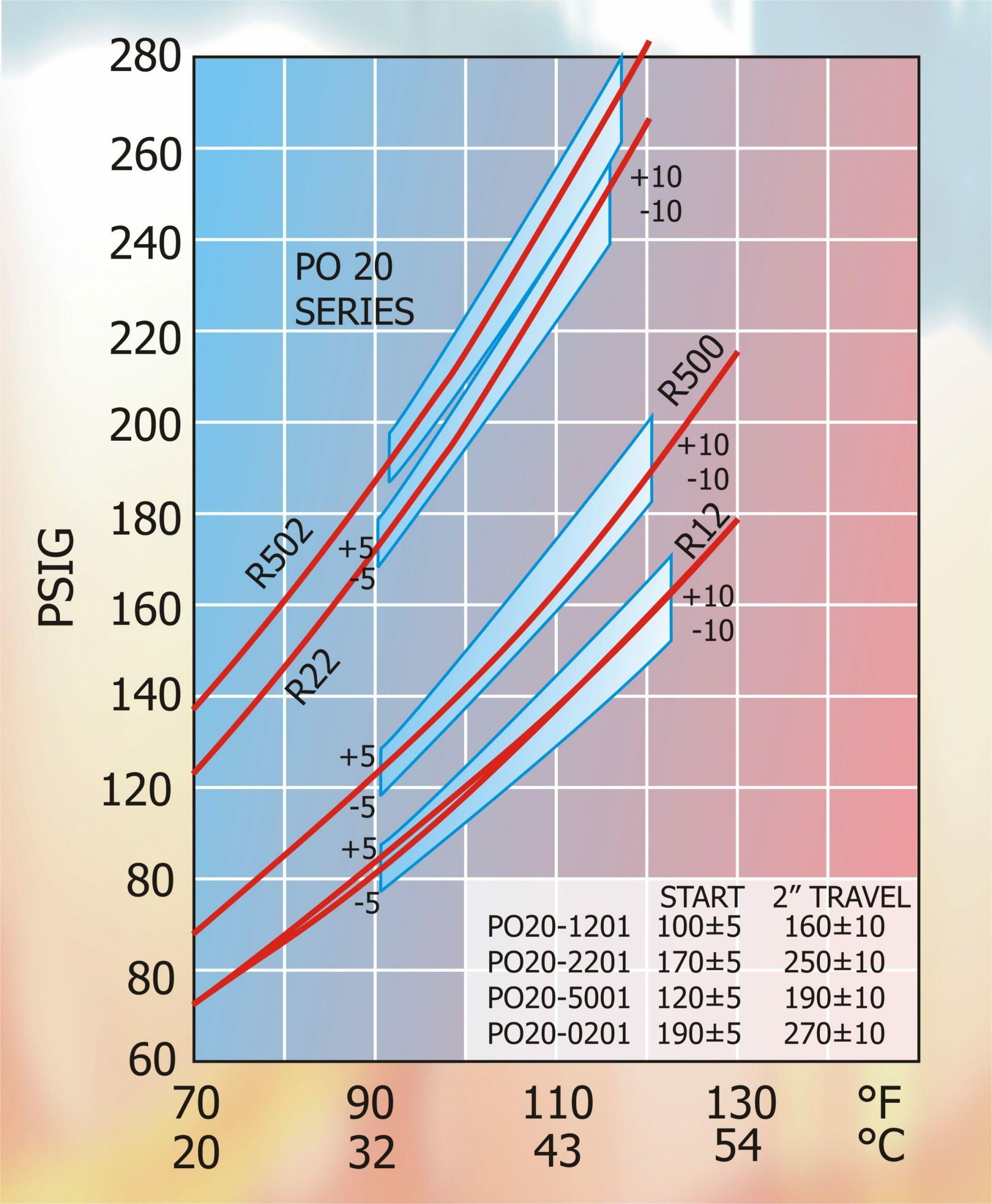
Figure 2.
It can be seen above that nearly 70% of the control of flow occurs during the first 30° of damper opening. Dampers are rarely called upon to operate in a fully closed position except under low ambient start-up conditions.
The closed position at this time aids in a much quicker build-up of head pressure. Robertshaw have many thousands of these actuators in the field installed over many years have found that ice and snow have little effect on the operation of the unit. The subject units have pull through horizontal fans with horizontally mounted dampers directly exposed to snow fall. It has been observed that condenser heat driven against the damper and snow or ice quickly melts the obstruction and allows normal operation of the pressure operator.
Torque & Positional Calculations
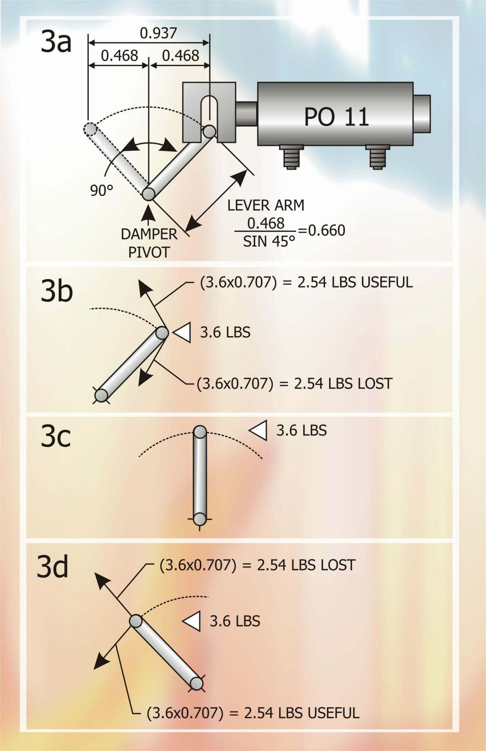
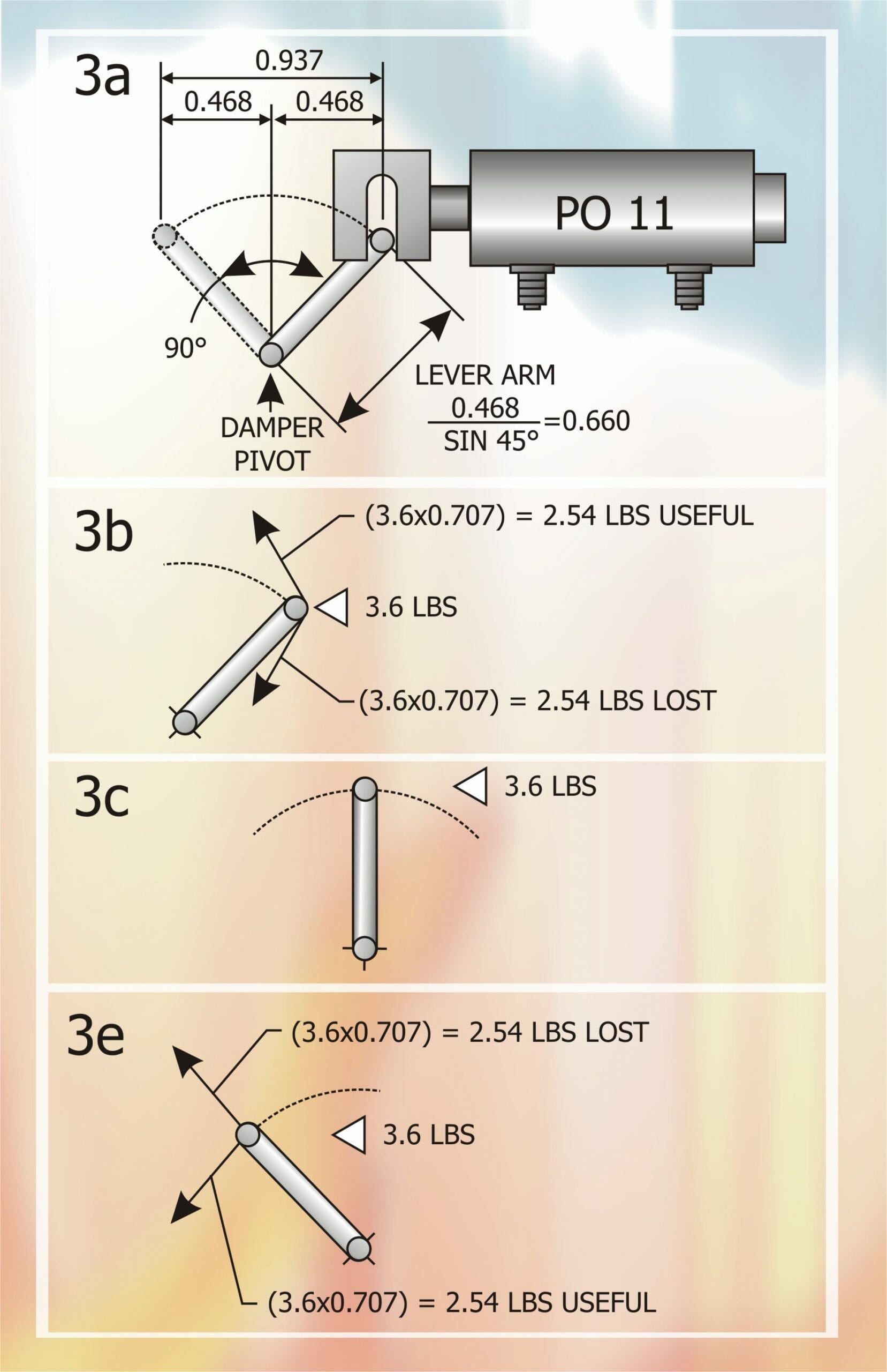
Figure 3a – The torque exerted at the shaft of the damper assembly varies according to the position of the pressure operator. Most damper designs require a 90 degree angular motion from closed to fully open position.
The example shown has a nominal travel of 0.937” and should be mounted to obtain half this travel before top dead centre and half after top dead centre. To obtain this, a lever arm 0.66” in length must be used.
The damper operator bellows have an area of 0.36”2 which will produce a thrust of 3.6 lb per 10 psi change in pressure.. The following show how this force can be expressed as torque, this being the required value for rating of damper assemblies.
Figure 3b – Start of Stroke – Pressure operator 3.6 lb. force per 10 psi is split into two components at the start of the stroke.
Figure 3c – Mid-Point of Stroke – The 3.6 lb. Force per 10 psi act directly on the 0.66” arm. Torque at this point is 3.6 x 0.66” = 2.38 in.lb.
Figure 3d – End of Stroke – Pressure operator 3.6 lb. force per 10 psi is split into two components at the end of the stroke. Torque at this point is 2.54 x 0.66” = 1.68 in.lb.
Fan Operation
Many propeller type fan blades have operational characteristics which tend to load the fan motor beyond its rated capacity when air flow is completely blocked. Field applications should be checked for this condition. Motor amperage measurements should be taken with the damper blocked shut to be sure the maximum rated fan current is not exceeded. Should this condition exist, there are several means of alleviating the problem. First, the damper may be blocked or stopped at the minimum flow condition which does not overload the fan. This will generally allow desirable head pressure control except in the most severe low ambient conditions.
Another solution is to control fan operation through a pressure control which will open the fan motor control circuit thereby stopping the fan when liquid line pressure has decreased to a value slightly above that where the fan motor will become overloaded. The control cut-in value should ordinarily correspond to a pressure slightly above the full open position of the damper. The best solution, and the one used by most original equipment manufacturers, is to provide the condensing unit with a fan which has non-overloading characteristics and therefore creates no problem. Centrifugal blowers are not subject to this problem.
Installation Precautions
Pressure connection to a condensing unit should be made in the liquid line or receiver to prevent damage to the bellows from compressor pulsations. Protection from the weather should be used to prevent water from entering the control at the shaft end, mount control with shaft in downward position. Damage to the bellows could result from water freezing inside the control. Naturally, brazing torches should not be applied to the body of the damper operator.
NEXT MONTH: Volume 27 – Control, Safety & Protection Devices used in the Vapour Compression Cycle continued.
DISCLAIMER: Whilst every effort is made to ensure absolute accuracy, Business Edge Ltd will not accept any responsibility or liability for direct or indirect losses arising from the use of the data contained in this series of articles.
