 Cassette Split Systems
 Safety Gloves
 UV Leak Detection
 Condensate Drain Pipe
 Nitrogen Regulators
 Filter Driers
 Filter Cores for Core Shells
MASTERCLASS – AIR CONDITIONING TECHNOLOGY
Volume 25 – Low Ambient Control for Single and Multiple Fan Condensers on Air Cooled Systems
In last month’s article we continued our study of Control, Safety & Protection Devices used in the Vapour Compression Cycle by considering the adverse behaviour of the refrigeration cycle under low ambient conditions and how this can be avoided. We now continue our study of the various means of providing Low Ambient Control for single and multiple fan condensers on air cooled systems.

One Fan – Single Phase – Air Cooled Systems
Low Ambient Control of single fan air cooled systems is best achieved by the application of variable airflow by means of variable fan speed control. In addition to maintaining the desired head pressure, the condenser fan speed control also assures minimum fan noise under all operating conditions. Since the condenser fan speed and resultant airflow will only be that required to maintain adequate head pressure, the fan will operate at lower speeds resulting in reduced noise, especially under low ambient conditions.
As it is the high side system pressure that we wish to maintain at a suitable level during cold external conditions, the ideal property to directly measure for control is the high side pressure. This can be achieved by use of a pressure transducer which reads pressure and converts this to a measurable electrical signal (0 – 10V or 4 – 20mA are common). Pressure Transducers have reduced in price substantially over the last ten years but are still considered too expensive by most manufacturers for small systems.
The use of a low cost temperature sensor positioned on the liquid line leaving the condenser coil is therefore usually used. This does however result in the sensor reading a sub-cooled liquid temperature rather than the condensing temperature. Moreover, there are delays between in a change to fan speed / airflow / high side pressure and the change in temperature reading at the liquid line due to system thermal inertia since the liquid in the base of the condenser must make it’s way to the sensor. This response time will also vary if the system is incorrectly charged.
The control algorithm in the software of the electronic controller must be carefully written to control the fan correctly or serious hunting of the fan will occur.
It is also possible to consider positioning of the temperature sensor on the bends of the condenser coil. This can be achieved by brazing a small tubular pocket, in which the temperature sensor is located to one or more bends of the coil. This has the advantage of reading a coil temperature that can almost be directly related to the saturation temperature (condensing temperature) of the refrigerant in the coil. Positioning of the sensor is very important to ensure that it does not read super-heated vapour in the upper region of the coil or sub-cooled liquid at the base. Theoretically, the majority of the condenser coil surface should contain saturated vapour in the process of converting to saturated liquid at a common temperature and a stable control should therefore be attainable. Changes in the amount of charge in the condenser, the circuiting of the condenser coil (which may also have to serve as an evaporator in heat pump applications), and other parameters can result in unstable operation and some manufacturers therefore avoid this approach.
Heat transfer paste should be used around the temperature sensor to ensure close agreement in pipework temperature and the surface of the sensor. The sensor must be located at the point recommended by the manufacturer.
Hard Start
In low ambient conditions, the motors can become very cold, particularly during the night if the system has been shut down. This causes contraction of various materials within the motor to occur at different rates which can lead to increased resistance to starting the motor. The lubricants within the bearings can also experience considerable increase in viscosity, thereby increasing the required starting torque.
The condensing unit may be positioned where a prevailing wind cause the condenser fan and motor to free-wheel in the opposite direction to normal running (wind-milling).
The low ambient controller will at this time be sensing a low temperature and would therefore attempt to start the fan at low rpm. The resistance imposed by any of the above, might prevent the fan form starting at all, leading to potential motor damage or tripping of the motor overload. The software routines in the low ambient control elements of the controller should cater for this and this is incorporated in the controllers illustrated in
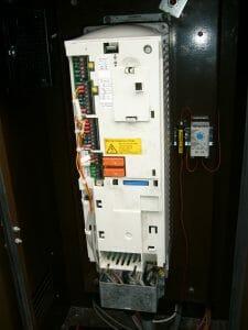
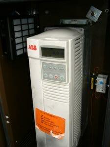
Figures 1 & 2 above.
One Fan – Three Phase – Air Cooled Systems
When it comes to larger systems, the increased airflow demands use of 3 phase motors. Low ambient control principles are applied in exactly the same way as for single phase motors with the following exceptions:
- a) The low ambient control electronics are much more complex as three phases are now being controlled.
- b) The relative cost of a pressure transducer is less prohibitive thus allowing this to be used for direct measurement of the high pressure which is after all the primary parameter to be controlled.
