 Cassette Split Systems
 Safety Gloves
 UV Leak Detection
 Condensate Drain Pipe
 Nitrogen Regulators
 Filter Driers
 Filter Cores for Core Shells
Vol.5 Compressors
Author Mike Creamer, Business Edge Ltd
PART 5
COMPRESSORS
IN Vol.4 article we looked at refrigeration cycles. We shall now move on to the key components of the vapour compression cycle starting with the heart of the system – the Compressor.
COMPRESSORS FOR AIR CONDITIONING & REFRIGERATION
Refrigerant vapour compressors fall into five principal types:
1. Reciprocating
2. Scroll
3. Screw
4. Rotary Vane
5. Centrifugal
Reciprocating Piston Compressors
The reciprocating piston compressor is still by far the most widely used being employed in all fields of commercial refrigeration, process cooling, industrial refrigeration, close control and comfort air conditioning.
Early models of refrigeration compressors were of the so-called Open Drive type, with the pistons and cylinders sealed within a crankcase. The crankshaft extending through the body for connection to an external power source. Open compressors are widely used for many applications. Open Drive compressors can be connected to a motor in Direct Drive arrangement using a flexible coupling or side-by-side for Belt Drive configuration.
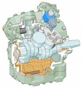
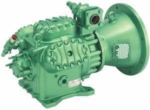
FIGURE 1 OPEN DRIVE COMPRESSOR CUTAWAY and FIGURE 2 OPEN DRIVE COMPRESSOR
The semi-hermetic compressor was pioneered by Copeland to overcome various difficulties including shaft alignment, seal failures, the short life of belts and direct drive components. The semi-hermetic compressor is driven by an electric motor mounted directly on the compressor crankshaft, with both the motor and the compressor working parts hermetically sealed within a common enclosure. The shaft seal is thereby eliminated and the motors can be specifically sized for the load to be handled. The resulting design is compact, economical, efficient and basically maintenance free. Removable heads, stator covers, bottom plates and housing covers allow easy access for field repairs.
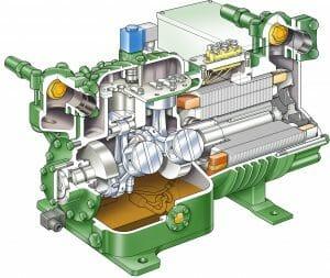
FIGURE 3 SEMI HERMETIC COMPRESSOR CUTAWAY
A small penalty in energy consumption will occur as the gas absorbing motor heat energy is expanded and the mass flow rate through the compressor is therefore reduced. Waste motor heat energy must also be rejected at the condenser and this component must be increased in size and capacity to allow for this.
The welded hermetic compressor represents a further decrease in size and cost, and is widely used in small horsepower unitary equipment. Again the motor is mounted on the compressor crankshaft, but the body is formed from a metal shell hermetically sealed by welding. No field repairs can be performed on this type of compressor.
The Compression Process
Before attempting to analyse the performance of compressors it is necessary to become familiar with the series of processes, which make up the compression cycle of a reciprocating piston compressor.
A compressor, with the piston shown as four points in its travel in the cylinder is illustrated in Fig.4. As the piston moves downward on the suction stroke, low-pressure vapour from the suction line is drawn into the cylinder through the suction valves. On the upstroke of the piston, the low-pressure vapour is first compressed and then discharged as a high-pressure vapour through the discharge valves into the head of the compressor.
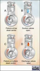
FIGURE 4 COMPRESSION CYCLE
To prevent the piston from striking the valve plate, all reciprocating compressors are designed with a small amount of clearance between the top of the piston and the valve plate when the piston is at the top of its stroke. The volume of this clearance space is called the Clearance Volume and is the volume of the cylinder when the piston is at top dead centre.
This means that not all the high-pressure vapour will pass out through the discharge valves at the end of the compression stroke. A certain amount will remain in the cylinder in the clearance volume region.
Reference to Figs. 4 and 5 will help to clarify the operation of the compressor. Figure 5 is a time-pressure diagram in which cylinder pressure is plotted against crank position.
At point A, the piston is at the top of its stroke, which is known as top dead centre. When the piston is at this position, both the suction and discharge valves are closed. The high pressure of the vapour trapped in the clearance space acts upward on the suction valves and holds them closed against the pressure of the suction vapour in the suction line.
Because the pressure of the vapour in the head of the compressor is approximately the same as that of the vapour in the clearance volume, the discharge valves are held closed either by their own weight or by light spring loading.
As the piston moves downward on the suction stroke, the high-pressure vapour trapped in the clearance space is allowed to expand. The expansion takes place along line A-B so that the pressure in the cylinder decreases as the volume of the clearance vapour increases. When the piston reaches point B, the pressure of the re-expanded clearance vapour in the cylinder becomes slightly less than the pressure of the vapour in the suction line; whereupon the suction valves are forced open by the higher pressure in the suction line and vapour from the suction line flows into the cylinder. The flow of suction vapour into the cylinder begins when the suction valves open at point B and continues until the piston reaches the bottom of its stroke at point C. During the time that the piston is moving from B to C, the cylinder is filled with suction vapour and the pressure in the cylinder remains constant at the suction pressure. At point C, the suction valves close, usually by spring action, and the compression stroke begins.
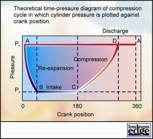
FIGURE 5 TIME PRESSURE DIAGRAM
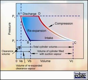
FIGURE 6 PRESSURE VOLUME DIAGRAM
The pressure of the vapour in the cylinder increases along line C-D as the piston moves upward on the compression stroke. By the time the piston reaches point D the pressure of the vapour in the cylinder has been increased until it is higher than the pressure of the vapour in the head of the compressor and the discharge valves are forced open; whereupon the high-pressure vapour passes from the cylinder into the hot gas line through the discharge valves. The flow of the vapour through the discharge valves continues as the piston moves from D to A while the pressure in the cylinder remains constant at the discharge pressure. When the piston returns to point A, the compression cycle is completed and the crankshaft of the compressor has rotated one complete revolution.
Efficiency Parameters
There are two basic efficiency parameters used to quantify the performance of reciprocating and the other positive displacement types. These are Volumetric Efficiency and Isentropic Efficiency. It is convenient to plot these values in the way shown in Figs 7 and 8 because they are primarily dependent on Pressure Ratio.
Volumetric efficiency is the ratio of volume of gas actually pumped to the theoretical swept volume of the compressor. This will be bore area x stroke x speed for a piston compressor. The effect of the clearance volume means that the volumetric efficiency is always less than 100% and decreases in a linear manner with pressure ratio. This is primarily due to the effect of the clearance volume. As will be described later, scroll and screw compressors can have higher volumetric efficiencies because these types have no clearance volume.
Isentropic efficiency is the measure of energy efficiency. It is the ratio of ideal gas compression power to actual absorbed power. The major energy losses arising in compressors consist of friction losses, flow losses, heat losses and electrical motor losses. These will vary to some extent from one compressor type to another and so the isentropic efficiency may typically be in the range 60% – 80 %.
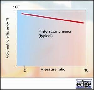
FIGURE 7 VOLUMETRIC EFFICIENCY
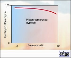
FIGURE 8 ISENTROPIC EFFICIENCY
For open compressors, shaft power input is used and for semi-hermetic and hermetic types, electrical power input is used and this must be taken into account if the efficiencies of the two types are compared.
Development of the piston compressor and new technologies
From the beginning of vapour compression refrigeration, piston compressors have been the workhorse of the refrigeration, air conditioning and heat pump markets. Piston compressor technology has traditionally offered good efficiency levels and, through proper design and application, piston compressors have become very reliable. In addition, the design and operating parameters of piston compressors are well developed and understood and the technology presents no particular manufacturing problems.
Industry demands placed on systems are changing and the requirements of compressors changing accordingly. Competition, high energy costs and environmental considerations are compelling manufacturers to develop even more efficient systems for the future. To do this cost effectively (for example, without inordinate heat exchanger size) will require compressor efficiencies higher than current reciprocating piston compressor technology can achieve. System sound levels are of increasing concern, with an increasing number of local regulations placing tighter restrictions on the sound levels of systems.
These demands have lead some compressor manufacturers away from piston compressor technology to more advanced compressor technologies.
NEXT Vol.6: More on compressors.
