 Cassette Split Systems
 Safety Gloves
 UV Leak Detection
 Condensate Drain Pipe
 Nitrogen Regulators
 Filter Driers
 Filter Cores for Core Shells
MASTERCLASS – AIR CONDITIONING TECHNOLOGY
Volume 36 – Air Handling
Chapter 35 discussed methods of establishing the quantity of air that had to be circulated to remove excess heat from a given space. We now need to consider the various methods of circulating the air and the constraints that determine our choice of Air Handling.
Air Handling
Product cooling, refrigeration and air conditioning all rely on forced air to transport the cooling or refrigeration effect. Here we will concentrate on air conditioning while discussing Air Handling Units (AHU’s) together with the environmental impact on the occupants of the conditioned space.
Before selecting an AHU the following aspects and questions must be considered;
Noise:
Will the noise from the AHU intrude on the environment? While it is possible to install a unit that is virtually silent, the cost will be greater than an AHU of higher noise level. If the application is a factory or busy office where the background noise level is fairly high, then a near silent unit cannot be justified. However, if the application is a theatre, lecture hall or broadcasting studio, then noise is of paramount importance.
Vibration:
Can the vibration from the AHU be absorbed by the building structure with out causing damage or nuisance in adjoining areas?
Air Outlet:
Will it be possible to locate the air outlet(s) so that the entire space to be conditioned can be controlled thereby avoiding stagnant air zones and/or draughts?
Heat Load:
Is the heat load in the conditioned space evenly distributed and do the primary heat sources remain in the same place during the entire time the area is occupied? In some applications that involve say, an open plan office, the office machinery may be grouped together in one area or it may be an office where the solar gains peak at different times of the day on different sides of the room. Therefore, the amount and distribution of air entering the office must match the varying heat load.
Plant Space:
Plant space would normally include both the physical space required by the AHU’s and the additional space required for duct work. Is the ceiling sufficiently high to accept ducting without intruding unacceptably on the aesthetics of the room? Can the wall perimeter be used or does the wall construction or window design prohibit their use? If a central AHU is being considered, is there sufficient space to accommodate such a unit and is it close enough to be practical?
Services:
Are there adequate services available or will the cost of providing the necessary services, such as electrical supplies, water and drainage influence the choice of AHU?
All of the above aspects must be considered when choosing the type of AHU’s to be used for the project.
Important Design Considerations
Since the design or selection of heat exchangers is invariably based on the assumption that the total volume of air entering the heat exchanger is at a uniform condition in terms of percentage saturation and temperature and that the total volume leaving the exchanger will also be at a corresponding uniformity. It is essential that AHU’s that have the facility to accept re-circulated return air from the conditioned space and the introduction of fresh air are capable of mixing these two streams of air into a homogeneous condition. Failure to achieve a homogeneous mixture will result in an uneven heat load on the heat exchangers and stratification of air leaving the heat exchanger.
The design of the air mixing chambers on an AHU must ensure that there is a uniform velocity of the air passing onto the next component in the air stream. For example, if the next component is a filter, uneven velocity will result in uneven clogging of the filter. This could result in the pressure differential switch, which gives a warning of filter blockage, failing to operate effectively. In another instance, if the next component is a heat exchanger, uneven air flow will result in the exchanger failing to perform and deliver to the original design conditions.
The choice of Air Handling Units is extremely wide and each type has its pros and cons. Therefore, to simplify the topic, we will group them into the following categories;
1] Central Air Handling Unit
2] Fan Coil Units
3] Integral Units
Each of these categories covers a wide variety of applications, ranging from domestic duty, typically 0.75kW to 6.0, to large industrial installations with duties of many hundred kilowatts.
CENTRAL AIR HANDLING UNITS (Fig.1)
These units provide all the conditioned air that is circulated around a building. This type of unit tends to be used for Theatres, Cinemas, Factories and Large Open Plan Offices. The units can be used for simple comfort cooling or can be very sophisticated and be used on applications that require very accurate control of temperature and humidity such as Standards Rooms and Environmental Test Chambers. These units are also suitable for total fresh air systems i.e. the application requires 100% fresh air, with no re-circulation.
Because of the type of applications that Central Air Handling Units are usually connected to, they tend to be physically large and as a consequence are usually located remote to the space they are conditioning.
A Central Air Handling Unit is more likely to be tailor made for a given project although they are available as standard units which comprise of a number of modules, each module providing a particular function. The standardisation of these units usually applies to the main module casing. Other major components such as heat exchangers, filters, etc. are designed for the specific requirements and duty.
The example of the Central Air Handling Unit shown as fig.1 could have been made up of seven modules.
Module 1 would be the fresh air / return air mixing chamber complete with damper assemblies.
Module 2 – the filter chamber.
Module 3 – the pre-heater.
Module 4 – the spray chamber.
Module 5 – the cooling coil.
Module 6 – the by-pass chamber with re-heater battery and damper assemblies.
Module seven – the fan assembly.
The cooling plant could either be a DX refrigeration system (DX coil connected to remote or integral condensing unit) or a chilled water/glycol solution unit (Chilled water coil connected to one or more water chillers. The glycol solution is intended to protect the system from sub-zero temperatures where the water chiller and/or Central Air Handling Unit is mounted externally. Heating cand be achieved using either electrical heaters, hot water or steam heater batteries. All these services would be piped to the AHU either from adjacent plant rooms or remote locations.
This type of central AHU can be constructed of sheet metal, suitably treated so that it is weather-proof and located externally or it can be purpose built within a building, with the various chambers being constructed from conventional building materials. Obviously the heat exchangers and filter units would be constructed by specialist manufacturers.
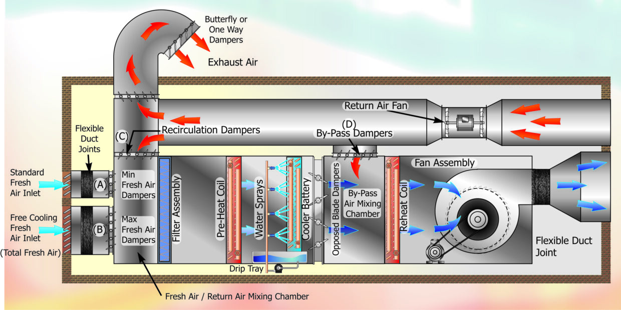
Fig 1
The advantages of this type of unit are;
All major controls are located within the AHU or closely adjacent.
Maintenance, all mechanical components including filter replacement are contained in the AHU which simplifies fault diagnoses, including refrigerant and water leak detection.
The need to work into occupied spaces is significantly reduced and is usually limited to adjustment of louvres and inlet/outlet dampers.
Plant noise is easier to control as there is more space to accommodate silencers and anti-vibration fittings.
Flexibility of construction and layout allow easy incorporation of many combinations of components and controls. For example:
- Simple filters.
- Absolute filters.
- Odour removing carbon filters.
- Electrostatic filters.
- Air washing spray chamber.
- Air cooling / humidifying spray chambers.
- DX evaporators.
- Chilled water coolers.
- Electric, hot water or steam heating.
Heat recovery can be more efficiently incorporated. Heat recovery may comprise of fresh air to exhaust air heat exchangers or it could be in the form of heat pump-condenser recovery coupled with plate to plate heat exchangers.
The disadvantages of this type of central AHU are as follows;
- This types of AHU is physically large and requires careful planning in terms of a suitable location.
- The space required for ducting and the corresponding holes through building fabric require careful co-ordination with builders and other mechanical services within the room.
- Rooms with variable or moving sources of heat gain such solar gain traversing around the room require sophisticated duct work and controls. Zone heaters may have to be incorporated into duct branches.
- More difficult to alter room usage, e.g. Subdividing an open plan office into a partitioned office or alter location of heat sources.
- Visually intrusive if located externally.
Fan Coil Units (Fig.2.)
The Fan Coil Unit is essentially what the name implies. The product basically consists of a water cooled heat exchanger and fan assembly, incorporating a filter and simple controls, designed for use as wall perimeter units, wall or ceiling units and units mounted within ceiling voids which can be connected to discharge diffusers by flexible or rigid ductwork. In this case, the ceiling void acts as a return air plenum.
Fan Coil Units can also be configured in the form of a ceiling cassette having a rectangular or circular shape. As a cassette unit they would draw air into the centre and discharge along the periphery.
These units can incorporate various forms of heaters (electric, hot water or steam). They will include some form of filtration although the range and efficiency of the filter is likely to be limited by the physical space available.
They can be controlled as individual modules or in groups.
The one aspect they all have in common is that the cooling (and heating) medium will be piped to each module from some external source.
The Fan Coil Unit shown in fig.2 is shown as a wall mounted item. However, it is not difficult to envisage the same configuration as a ceiling unit. It would be necessary to reposition the drip tray and return air grille and filter but essentially the layout would be very similar.
Advantages of this type of system are;
- They can be individually controlled and therefore provide control for a zone or an individual office.
- They are a relatively low cost items, which are mass produced in a standardised form.
- All operating parameters have been established in test chambers.
- Individual units can provide heating while others are providing cooling.
- Control system are simple and do not require highly skilled specialists to service the unit.
- Standby capacity is built in, as much that each unit represents a small percentage of the total cooling capacity and if one should fail the effect is not catastrophic.
- Capital cost is usually lower than other type of system of similar capacity.
Disadvantages for this system are;
- There is very limited flexibility in the performance of each unit as all operating parameters are fixed at the time of manufacture.
- With the exception of specialist units, these units can only provide dry bulb control of the simplest nature. (The specialist units referred to are the type fitted to computer rooms or test chambers. They incorporate electronic control systems, humidifiers, and advanced filtration).
- Control of fresh air input, if available, is very limited and consequently the ability to utilise free cooling is not an option.
- Noise levels can be higher than central AHU’s.
- The ability to control air distribution can be limited.
- This type of unit is always visible (With the exception of the above ceiling units which supply air to diffusers via ducts.)
- The connecting services such as chilled water or refrigerant pipe work together with condensate pipe work can be difficult to conceal.
- Maintenance and servicing of these units can cause disruption to the occupants, and the risk of damage to the fabric of a room is greater by virtue of all the services and their connections being within the room.
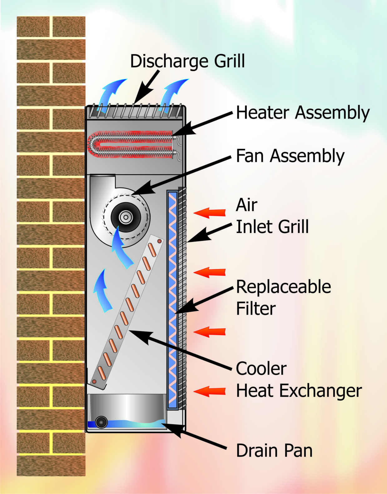
Fig 2
Integral Units
A unit is defined as an Integral Unit when all the system components are combined into one complete package.
The type of system most people are familiar with, are the “through the window units” seen in individual offices, small shops and domestic locations. These units are usually in sizes from 0.75 kW to 6 kW. However, similar systems are available on a much larger scale (50kW to 100 kW), and are frequently installed over large open areas such as supermarkets, warehouses and factories. Each of the large integral units would provide zone control.
As with most integral units they can be installed as heat pumps by simply reversing the plant operation. It is common practice to install a large number of units for a given duty so that the zones they control can have a more precise control and in the event of a failure of a unit only a relatively small percentage of the total cooling / heating capacity is lost.
Integral unit systems are available for wall, roof as well as through the window fixing. The larger units can supply air through ducts with the return air entering the units via plenum voids. Although the small to medium sized systems have limited fresh air control, the larger units can provide up to 100% fresh air.
Advantages of the integral units are;
- Lower first cost than central systems.
- The practice of using multiple units for a given load provides a high level of standby.
- Units can provide individual heating or cooling thereby matching load variations around a conditioned space.
- Heat pump operation can be incorporated.
- Can offer space saving by avoiding or reducing the need for ductwork.
Disadvantages of integral units are;
- Holes through building structure can be large.
- Noise levels are high when plant is operating at optimum performance levels. Reductions in noise often require significant reductions in plant capacity.
- Humidity control is limited.
- Requires frequent maintenance compared to central systems.
- Requires considerable surface area external to the conditioned area to allow adequate spacing between units.
Although the description of each of the categories of air handling system has been treated in isolation, in many projects combinations of the categories are common and it is up to the design engineer to identify the ideal combination for any given project.
NEXT MONTH: VOL 37 – Selection and Design of Ductwork
DISCLAIMER: Whilst every effort is made to ensure absolute accuracy, Business Edge Ltd. will not accept any responsibility or liability for direct or indirect losses arising from the use of the data contained in this series of articles.
