 Cassette Split Systems
 Safety Gloves
 UV Leak Detection
 Condensate Drain Pipe
 Nitrogen Regulators
 Filter Driers
 Filter Cores for Core Shells
Last month completed our review of compressor lubrication. We now move on the subject of Capacity Control – matching system capacity to varying load conditions.
Why is Capacity Control necessary?
There are a number of reasons for incorporating capacity control into a system and they all essentially compensate for a reduction in system load which results in surplus plant cooling capacity.
Many applications will experience solar gains where external surfaces apply. The variation in solar gain alone can be very substantial and where a number of rooms or loads are connected to one central plant, condensing unit or chiller, load variations will be even more dramatic.
Therefore, most systems for a wide range of applications will operate at some time with a cooling load which is less than the calculated maximum design load and when this happens the plant will rapidly cool the conditioned space and then be switched off by a thermostat or perhaps some form of electronic controller. However, under certain conditions the room temperature will rise rapidly and cause the thermostat to switch the plant on again. This sequence of events will repeat frequently and can result in excessive cycling of the plant, which in turn will have an adverse effect on plant reliability, particularly the compressor drive motor. In addition, the temperature fluctuation within the conditioned space may become noticeable and result in discomfort. Such variation in temperature will be unacceptable for certain applications.
In extreme conditions, the system load can reduce so rapidly that the fall in evaporation temperature and suction pressure can cause the low pressure switch to operate before the room thermostat. If this occurs, the plant will cycle on the low pressure switch and since this is normally an auto-reset protection device, the subsequent short cycling will cause damage to the compressor motor.
In order to avoid the conditions described above it is necessary to compensate for the varying loads by adjusting the system capacity to match the instantaneous load on the refrigeration system. When the term “capacity” is used, this actually refers to the mass flow of refrigerant vapour that is passing through the compressor. Therefore, if a compressor is operating at 50% capacity, it means that when compared to its fully loaded condition it is pumping 50% of the design mass flow of vapour.
In the case of a conventional positive displacement reciprocating compressor, the mass flow of vapour is determined by the following factors:
- Refrigerant Type
- Cylinder Bore
- Piston Stroke Length / Crankshaft Throw
- Volumetric Efficiency (1)
- Specific Volume (or Density) of Vapour (2)
This varies according to compressor design, speed, manufacturing quality, clearance volume, suction pressure, discharge pressure, superheat, etc.
2) This varies according to suction pressure and superheat
There are a number of ways to adjust system capacity and we will look at them in terms of energy efficiency, commencing with the least energy efficient method.
REHEATING AND PREHEATING
This method utilises a heater battery, either electric or steam/hot water, fitted within the air-handler or ductwork, usually after but sometimes before the evaporator coil, with the objective of maintaining fixed load at the evaporator coil. As the heat load in the conditioned space falls, so more heat energy is applied by the heater battery. This then maintains a reasonably constant off-coil outlet temperature, which in turn maintains dry bulb air temperature entering the evaporator close to the design condition. The heater battery can be controlled by a modulating controller sensing the reduction in air temperature, gradually increase heat output as required. However, this mode of operation will dehumidify the conditioned space since the evaporator will be running at maximum capacity. This dehumidification may then to be compensated for by increased use of the humidifier.
In terms of energy usage this type of system is the least efficient, because an artificial load is applied to the system. The refrigeration plant therefore operates continually at full load. Moreover, the heater battery increases overall power consumption as does the humidifier. The only advantage with this type of system is its simplicity and the fact that dry bulb temperature can be precisely controlled to a fraction of a degree by the heater controller.
DISCHARGE GAS BYPASS.
Discharge Gas Bypass is another simple and effective method of matching plant capacity to the cooling load. This method injects hot discharge gas from the compressor(s) into the low side of the system, thereby maintaining a minimum suction pressure and its equivalent saturation temperature. However, if the discharge gas is injected into the suction line and no attempt is made to control the temperature of the superheated suction vapour, the result would be a rapid rise in discharge gas superheat and temperature, to the extent that lubricating oil would carbonise and the compressor would ultimately seize. FIG 1
Where hermetic or semi-hermetic compressors are concerned, the motor cooling is achieved by the flow of relatively cool, dense suction vapour over the motor windings. Again, if the temperature of the suction vapour is too high and the density too low through excessive superheating, inadequate motor cooling will result, causing nuisance trips of motor over-temperature / over-current devices and perhaps ultimate motor failure
A typical arrangement which compensates for excessive superheat is shown in Figure 2. A Bypass Line (A) is connected to the discharge line after the oil separator. This connection is positioned after the oil separator in order to reduce the amount of oil carried over to the low side of the system. The by‑pass line must be fitted with a hand shut off valve and, ideally, a solenoid valve followed by the discharge gas by‑pass valve. This valve is a constant pressure valve which responds to the pressure at its outlet port.
FIG 2

The hand shut-off valve enables the system to be pumped down and is used when diagnosing system faults and during commissioning. The solenoid valve is a safety feature to prevent vapour leaking through the bypass valve during the off-cycle, i.e. the valve is only energised and open when the compressor is running.
As the evaporator pressure falls due to the reduction in thermal load, the by‑pass valve will start to modulate open and allow discharge vapour to enter the evaporator downstream of the expansion valve at (B). The introduction of discharge vapour into the evaporator will provide the necessary heat energy to vaporise a portion of the liquid refrigerant flowing from the expansion valve. This injection of hot discharge vapour will also cause a rise in evaporator pressure and consequently the evaporation temperature. It will also increase the superheat of the vapour leaving the evaporator. The TEV phial (C.) will sense the increased superheat and open the expansion valve allowing more refrigerant to enter the evaporator which in turn will reduce the superheat of the vapour leaving the evaporator to the original value setting of the valve.
This type of control is suitable for smaller systems which use a single compressor to provide the cooling to one or more areas or where there is wide diversity in load. Interestingly, with discharge gas bypass control it is not necessary to connect all evaporators to the discharge bypass line, since a rise in pressure in the suction line will affect all the evaporators connected to the suction line. In effect, all evaporators will maintain a constant evaporation temperature. The rise in evaporation pressure will increase saturation temperature thereby reducing the overall performance of all evaporators.
A similar type of control can be used where a single compressor is connected to a number of evaporators which can be individually switched off. In this case, when the required temperature is attained in the space controlled by a specific evaporator, a thermostat closes a liquid line solenoid valve feeding liquid refrigerant to the evaporator. Using this approach, it is not necessary to fit each evaporator with a hot gas bypass valve. A single bypass valve injects high temperature discharge gas directly into the suction line and de-superheating is undertaken by a dedicated expansion valve feeding liquid into a Suction Line Accumulator. See Figure 2.
While it is possible and not unusual to inject hot discharge gas and de-superheating refrigerant directly into the suction line without any accumulator, it is considered good practice to fit an accumulator and this also acts as a mixing chamber and provides adequate room for the de-superheating liquid to evaporate and mix with the superheated vapour. In this application, discharge gas is injected into the suction line just prior to the accumulator, or directly into the accumulator (B), and a de-superheating expansion valve also feeds liquid refrigerant into the accumulator.
Two types of expansion valve are available for this type of de-superheating;
A conventional TEV, suitable for high back pressure applications, is fitted with the superheat adjustment set at maximum. The valve phial is fixed to the suction line, downstream of the accumulator, approximately 2 to 3 metres at (Z) from the compressor.
Alternatively, a direct discharge temperature sensing expansion valve feeds liquid refrigerant into the accumulator. This valve operates in the same manner as a conventional expansion valve, but the phial has been designed to sense high temperature discharge vapour at the compressor outlet at point (Y). It is therefore a more effective method of controlling discharge superheat.
In terms of energy efficiency, discharge gas bypass is marginally better than the re-heater methods previously described, but is still poor since the compressor continues to run at full load during the whole of each operating cycle. An advantage of the discharge gas bypass method over re-heating is that the air passing through the air handler is not excessively dehumidified due to the higher evaporating temperature thus saving energy. Therefore, further energy savings will be realised through reduced operation of the humidifier during low load conditions.
CYLINDER UNLOADING
On larger reciprocating compressors, the option to use cylinder unloading is often available. Cylinder unloading is achieved in a number of ways, the two most common methods being Suction Valve Control and Cylinder Head Bypass.
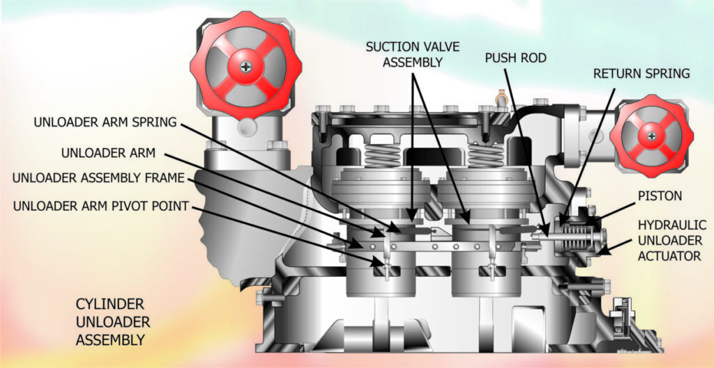
SUCTION VALVE UNLOADING
A common method of Suction Valve Control is to use the compressor oil pump to pressurise a hydraulic ram so that it lifts the suction valve assembly and allows the valve springs to keep the valve plate seated against the valve port. If oil pressure is removed from the ram, the valve assembly moves away from the valve plate and the valve seat no longer seals the valve port. When this occurs, suction vapour will flow into the cylinder during the suction stroke but, during the compression stroke, instead of being compressed, the vapour flows back into the suction manifold.
FIG 3

A typical arrangement is shown in Figure (3). This shows a part section of a multi-cylinder compressor and covers one bank of cylinders. The unloading mechanism is shown in an unloaded state, with the hydraulic piston pushed to the right by the piston return spring. The push rod, which is connected to the unloader piston, has pulled the unloader frame to the right and this has increased the tension on the unloader arm spring. This spring has pivoted the unloader arms to a near vertical position and forced the suction valve assembly to lift and move the suction valves away from their seats. When oil pressure is pumped into the unloader actuator, it enters the space above the unloader piston and forces the piston to the left, compressing the unloader return spring. As the piston moves to the left, it pushes the unloader frame to the left and this reduces the tension on the unloader arm spring, allowing the unloader arm to pivot anti-clockwise. This in turn allows the suction valve assembly to lower the suction valves onto their seats.
When cylinders are arranged in banks of two whether it be in “V” or “W” configuration it is normal to unload a complete bank rather than a single cylinder. Most compressor manufacturers insist on retaining one bank of cylinders fully loaded at all times in order to keep the crankshaft loaded. If not, the crankshaft would float within the bearing and lubrication control would be lost. The typical capacity control sequence with this type of configuration would be a four cylinder compressor, having two banks of cylinders and this would provide two steps of capacity, 50% and 100%. A six cylinder compressor having three banks would have three steps of capacity, 33%, 66% and 100%. This principle is maintained up to 16 cylinder compressors and beyond.
To implement capacity control, a pressure sensor would detect a drop in suction pressure and activate a step controller. This would open a three way solenoid valve connected to a bank of cylinders and bypass the oil away from the cylinder unloading ram, thus resulting in the suction valve assembly moving away from the valve plate and uncovering the suction valve port, thereby preventing any further compression. Conversely, if the suction pressure began to rise, the pressure sensor would reverse the step controller which in turn would close off the oil bypass valves to each bank of cylinders and the oil pressure would be returned to the unloading mechanism. The suction valve assembly would seat the suction valves against the suction ports in the valve plate.
CYLINDER HEAD BYPASS
As in cylinder unloading, cylinder head bypass is normally implemented on banks or pairs of cylinders rather than single cylinders. See the schematic diagram in Figure (4).
FIG 4

In this arrangement, a check valve is fitted between the discharge manifold and the discharge pipe. A connecting port is also fitted between the discharge and suction manifolds. This connecting port is fitted with a valve which is maintained in a closed position by oil pressure. If the compressor capacity has to be reduced, oil pressure is diverted from the connecting port valve by a three way solenoid valve, thus allowing the valve to open. When this occurs, the high pressure vapour in the discharge manifold equalises with the pressure in the suction manifold and no further vapour is pumped out of the discharge manifold. Suction vapour simply recirculates between the manifolds.
The two types of cylinder unloading described above allow the compressor to start in a fully unloaded condition. This is due to the oil pump requiring a minimum speed perhaps as high as 800 rpm before sufficient oil pressure is built up to activate the cylinder loading mechanism. Since there is substantial inertia to overcome within the drive motor and the compressor being driven, the inrush current (also know as start current or L.R.A. meaning Locked Rotor Amps) is normally several times greater than the full load running current. Many compressors also commence compression immediately at start up thereby increasing the starting current substantially. If the compressor can be started in an unloaded condition where the pistons are not compressing the refrigerant vapour during the start up phase, a standard motor can be used instead of more expensive high start torque motors.
In terms of energy efficiency, cylinder unloading represents an actual saving of energy during reduced capacity running. However the power reduction is not directly proportional to the reduced capacity of the compressor since compression losses and frictional losses will still be incurred. Therefore a compressor running at 50% capacity for example will only experience a reduction in power consumption by approximately 35%. Nevertheless, this is a significant improvement over hot discharge gas injection systems. Moreover, this order of magnitude of saving in energy costs sufficiently outweighs the additional cost of fitting cylinder unloaders.
DISCLAIMER: Whilst every effort is made to ensure absolute accuracy, Business Edge Ltd. will not accept any responsibility or liability for direct or indirect losses arising from the use of the data contained in this series of articles.
