 Cassette Split Systems
 Safety Gloves
 UV Leak Detection
 Condensate Drain Pipe
 Nitrogen Regulators
 Filter Driers
 Filter Cores for Core Shells
AIR CONDITIONING TECHNOLOGY
Volume 24 – Control, Safety & Protection – Low Ambient Control
Control, Safety & Protection Devices
In last month’s article we continued our study of Control, Safety & Protection Devices used in the Vapour Compression Cycle by covering the Low Pressure & High Pressure Cut-Out Switches. This month we move on to Low Ambient Control.
Low Ambient Control / Head Pressure Control
Most air conditioning products or systems are expected to operate during periods of higher summertime ambient temperature when the thermal load on the room increases the room temperature beyond the setpoint of the thermostat or other controlling product. Many air conditioning products and systems do not therefore require Low Ambient Control also known as Head Pressure Control.
However, some air conditioning products and systems are required to run occasionally or perhaps even continuously during the winter or mild periods as a result of the heat and thermal load generated internally such as with computers located in the conditioned space. Under these circumstances, it is wise to fit Low Ambient Control.
Low Ambient Control is normally available as an option on most air conditioning products or systems in order to avoid the costs of fitting this facility to equipment that will not require it.
Clearly, all refrigeration applications will have to run occasionally or continuously during mild and very cold ambient conditions and low ambient control since the desired temperature is always lower than normal surrounding air temperatures thus leading to transmission heat gain. The product load could also be frequent or continuous throughout the year. Low Ambient Control should therefore be considered for most refrigeration applications according to the circumstances.
Effects of Low Ambient on Refrigeration Cycle
All compressors create a difference between inlet and outlet pressure as well as circulating refrigerant around the refrigeration system. Typical pressures in an air conditioning system might be 5 bar suction and 15 bar discharge at the compressor. This results in a differential of 10 bar over the compressor and in this case the compression ratio is 3:1.
In order to explain the problems associated with low ambient conditions at the condenser, it is important to be aware of the following:
- Most fixed speed compressors will exert a lower suction pressure if the discharge pressure is reduced. Conversely, if the discharge (or head pressure) is increased, the compressor will not be able to exert such a low suction pressure.
- As the thermal load increases at the evaporator, the amount of liquid refrigerant evaporated is increased thus leading to an increase in the amount of saturated / superheated vapour being generated. In the case of a fixed speed compressor, the pressure in the evaporator will rise as the thermal load rises. Clearly, the pressure in the evaporator will fall as the thermal load reduces since the compressor will continue to run at fixed speed and capacity but there will not be sufficient vapour to satisfy it’s demands.
- As the outdoor ambient temperature falls, the part of the thermal load on the system evaporator(s) will also fall.
Under normal summertime ambient temperatures, the refrigeration cycle will be expected to create a sufficiently high discharge pressure to generate a refrigerant saturation temperature higher than the ambient temperature (say 10 K) in order to reject heat at the condenser. If the ambient temperature is 30 Deg C and the condensing temperature is 40 Deg C, the condenser coil will be sized to reject the correct amount of heat energy (say 100 kW) under these conditions.
Under these circumstances, the thermal load at the evaporator will be high, the compressor will exert the correct design suction pressure of say 5 bar, and, due to it’s compression ratio at these conditions, the discharge pressure might be 15 bar.
However, when the ambient temperature starts to fall, the following effects take place:
The difference between ambient temperature and the condensing temperature, which was 10 K, begins to increase.
This increase in temperature difference at the condenser coil causes the capacity and efficiency of the coil in rejecting heat energy to increase beyond 100 kW.
The increased effectiveness of the condenser coil causes the discharge pressure to fall because the superheated vapour entering the condenser is more effectively reduced to saturated liquid. The condenser coil is now considerably oversized.
The suction pressure at the inlet of the fixed speed compressor is reduced due to lower discharge pressure and this in turn reduced the pressure within the evaporator(s) and also the saturation temperature of the refrigerant within the evaporator(s).
The thermal load on the system at the evaporator(s) decreases due to low ambient temperature. Less refrigerant vapour is generated and the evaporator pressure and saturation temperature continue to fall.
The reduced high side discharge pressure is not quite as effective in driving the refrigerant along long horizontal liquid lines or vertical liquid lines and is less able to force the liquid refrigerant through the expansion device. The reduced pressure over the liquid refrigerant causes it’s saturation temperature to fall below that of it’s surroundings and partial evaporation of valuable liquid refrigerant occurs before reaching the evaporator coil(s). The evaporator pressure is therefore further reduced along with saturation temperature.
As the evaporator coil(s) get colder, more attention is dedicated to removing latent heat rather than sensible heat. The desired room condition becomes more difficult to achieve and the system is therefore forced to run continuously under these deteriorating conditions.
As the saturation temperature falls below 0.0 Deg C, moisture on the evaporator coil(s) starts to freeze. This causes a reduction in airflow with an attendant drop in thermal energy being delivered to the evaporator coil(s), thus leading top a further reduction in evaporator pressure and saturation temperature. The formation of ice also acts as an insulation to further reduce the transfer of heat energy to the liquid refrigerant within the evaporator coil(s).
There ultimately comes a point where there is excessive liquid refrigerant within the evaporator(s) and insufficient heat energy reaching the liquid to fully evaporate it. This excess liquid can the leave the coil, enter the compressor and cause liquid slugging resulting in substantial damage or destruction of the compressor.
Low Ambient Control for Air Cooled Systems
The solution to the problems just described is Low Ambient Control and the way in which this works is as follows:
The condenser coil of an air cooled system must be correctly designed and sized to cope with the maximum heat of rejection from the system. This will occur when the thermal load is at the highest level. This is almost certain to occur when the ambient temperature is also at a peak. The condenser coil will therefore have sufficient tubes and fin area to reject heat energy from the refrigerant entering the condenser at a reasonable temperature difference between ambient air and the condensing temperature of the refrigerant.
For example, if the peak ambient temperature is 30 Deg C and the condensing temperature is 40 Deg C, a temperature difference of 10K exists. Under these conditions the correctly sized condenser coil will ensure efficient performance from the compressor, good compressor life, low energy input and reduced CO2emissions. A generously sized coil also permits a lower airflow rate thus leading to reduced velocity, lower pressure drop, better contact time and lower noise levels.
The airflow can be calculated as follows:
THR (kW)
Airflow m3/s = ——————-
1.2 x (TE – TL)
Where:
THR = Total Heat of Rejection (kW)
TE = Entering Air Temperature (Deg C)
TL = Leaving Air Temperature (Deg C)
1.2 = Factor (*)
* The construction of this factor and many other formulae are planned for the psychrometrics section of this series at a later date.
If the THR is 100 kW, the required airflow for the example above is:
96 kW
Airflow m3/s = ——————- = 8.00 m3/s
1.2 x (40 – 30)
Under these circumstances, the system is correctly balanced at the correct condensing temperature which maintains the high side system discharge pressure at a sufficient level to avoid the problems described earlier.
However, if the ambient temperature falls and yet the thermal load within the conditioned space still requires cooling to be applied, the temperature difference between ambient air and the system condensing temperature will increase. This increase in TD (Temperature Difference) will proportionally increase the heat transfer efficiency of the condenser coil. The effect of this increased efficiency is a reduction in condensing temperature (and discharge pressure) since the condenser coil is now able to easily handle the THR as it is now very much oversized. The hot gas entering the condenser is rapidly de-superheated to the lower condensing temperature and the latent heat of condensation is removed very effectively. The resulting liquid refrigerant residing at the base of the condenser is then effectively sub-cooled. Moreover, part of the thermal gains to the conditioned space such as solar and transmission gains may also be reduced at this time, leading to further “over-sizing” of the condenser coil due to reduced THR from the system.
Low Ambient Control to offset these effects is normally achieved by modulation of condenser airflow
Since the TD (temperature difference) across the condenser coil directly affects the thermal efficiency, the airflow can be reduced as TD increases in such a way as to maintain the THR (Total Heat of Rejection) and thereby the condensing temperature and pressure. Taking the following example:
THR = 96 kW
Ambient Temperature = 0.0 Deg C
Desired Condensing Temperature = 40 Deg C
96 kW
Airflow m3/s = ———————- = 2.0 m3/s
1.2 x (40.0 – 0.0)
It can be seen from the above that whilst the temperature difference has increased by a factor of 4, reducing the airflow by an identical ratio from 8.0 m3/s to 2.0 m3/s maintains the same THR of 96 kW thereby holding the condensing temperature at 40 Deg C.
Control of condenser airflow can be achieved by the following methods:
1 Infinite modulation of fan speed in the case of a single fan condenser
2 Fan cycling (switching on and off) for multiple fan condensers
3 Fan cycling + infinite speed modulation of a single fan for multiple fan condensers
Infinite modulation of fan speed – single fan condenser
In the case of a single fan condenser, the fan speed can be infinitely modulated to maintain the desired condensing temperature and pressure. Since it is the pressure that we primarily wish to control and maintain, it should be the pressure that is monitored and used to control fan speed. In the case of larger systems, particularly where 3 phase fan motors are fitted, a pressure operated controller is utilised. However, on smaller systems, the costs associated with the pressure transducer and associated electronics is too prohibitive. Temperature is therefore used as a close measure of prevailing high side condensing pressure since these are directly related for every refrigerant.
Some manufacturers place a temperature sensor on one or more hairpin bends of the copper tubes of the condenser coil in order to read condensing temperature. The fan speed is then controlled to automatically maintain this temperature as closely as possible. In theory, the temperature sensor should be placed in the latent region of the coil to correctly read condensing temperature. The sensor must not be allowed to read de-superheating vapour entering the top of the condenser.
Placing the sensor on the liquid line immediately leaving the condenser coil is an alternative used by other manufacturers. However, since sub-cooled liquid exists at this point it is necessary to compensate the setpoint temperature used for control of the fan speed. This method eliminates the possibility of hot gas presence at the temperature sensor which may occur for various reasons including under-charging. The liquid line should provide a more stable condition for control of the fan speed but can have the disadvantage of time lag where the change in fan speed and condensing temperature takes some time to register at the liquid line.
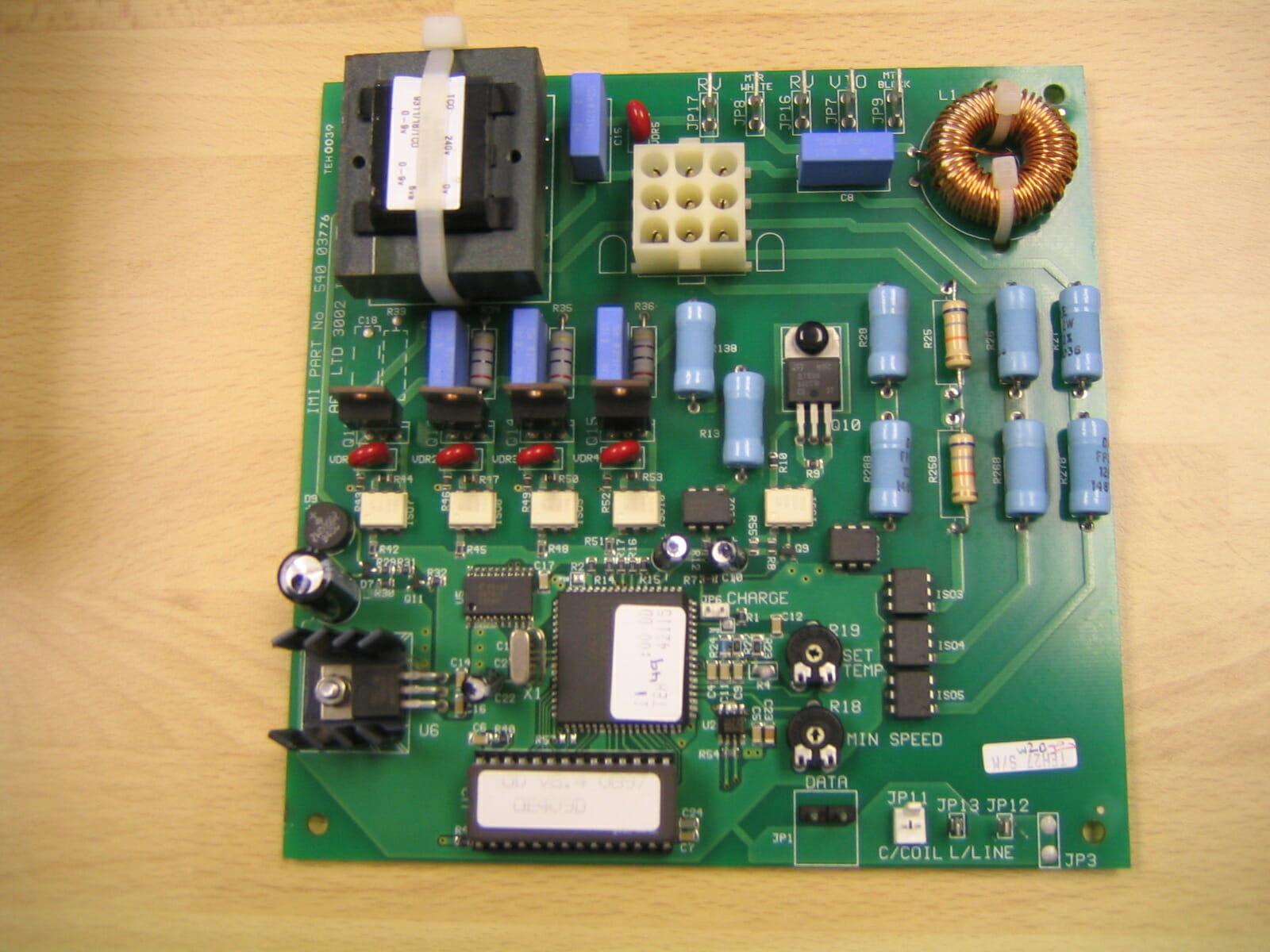 Figure 1 NEIL – Caption to read: Outdoor Board With Low Ambient Control Kit.
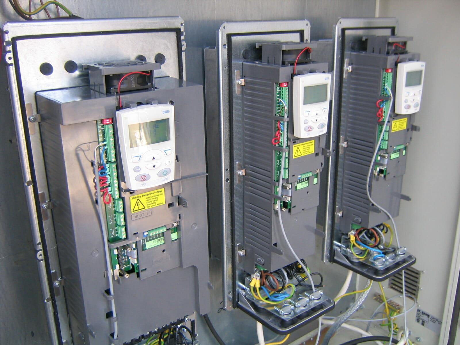 Figure 2 NEIL – Caption to read: 3 Power Inverters for Pressure Driven Low Ambient Control
NEXT MONTH: Vol 25 – Control, Safety & Protection Devices used in the Vapour Compression Cycle continued.
DISCLAIMER: Whilst every effort is made to ensure absolute accuracy, Business Edge Ltd will not accept any responsibility or liability for direct or indirect losses arising from the use of the data contained in this series of articles.
