 Cassette Split Systems
 Safety Gloves
 UV Leak Detection
 Condensate Drain Pipe
 Nitrogen Regulators
 Filter Driers
 Filter Cores for Core Shells
Vol 23 – Control, Safety & Protection Devices (Continued)
Author Mike Creamer, Business Edge Ltd
AIR CONDITIONING TECHNOLOGY
Volume 23
Control, Safety & Protection Devices
In last month’s volume 22 we commenced a study of Control, Safety & Protection Devices used in the Vapour Compression Cycle by covering the Thermostatic Switch and the Low Pressure Cut-Out. This month we continue with the application of the Low Pressure Cut-Out and move on to the High Pressure Cut-Out and other devices.
As stated earlier, the Low Pressure Cut-Out switch can be used to regulate the desired temperature within the conditioned space. The differential setting of the Low Pressure Cut-Out will vary according to the level of accuracy required. A wide pressure differential will allow some variation room, coldroom or display case temperature. This will also increase the length of the operating cycle of the compressor which effectively means the compressor will not run as often but would run for longer periods to in order to traverse the switch differential and restore the original setpoint.
This is a more desirable situation on terms of compressor life as a result of the reduced number of starts. The increased run time of the compressor throughout each cycle will ensure good motor cooling in the case of hermetic and semi-hermetic machines and the overall cycle efficiency would be improved. A differential set to close limits however, would cause the reverse of the aforementioned but would provide closer space temperature control.
The pressure difference between the cut-in and the cut out points varies with the refrigerant used.
Protection against Refrigerant Leakage
The Low Pressure Cut-Out Switch is available in both Auto and Manual Reset versions, although the Auto Reset version is most commonly applied. The reasons for Auto versus Manual Reset are explained later in this article.
The Low Pressure Switch provides protection in the event of a refrigerant leak by tripping at a low pressure setting commensurate with the loss of all liquid refrigerant from the system. The remaining vapour falls in pressure and once the Low Pressure Switch has tripped, preventing compressor operation, the system cannot restart until the problem has been resolved by repairs and recharging. This prevents the primary enemies, air and moisture, being drawn into the system.
Nuisance Tripping
Under cold ambient conditions, the Low Pressure Switch will often operate shortly after the compressor starts thereby disabling the system’s ability to meet cooling demand. This is sometimes referred to as nuisance tripping.
Nuisance tripping of the LP Cut-Out is caused when the system attempts to start with a very cold condenser coil or cold condenser water in the case of a water cooled system. When the compressor is not operating, the system high and low side pressures are normally equal and this is known as the standing pressure. All systems experience an immediate drop in low side pressure and an increase in high side pressure as the compressor starts and under normal circumstances where the condenser coil is located in warm ambient air the LP Switch will not trip.
However, when the condenser coil is cold it is easily able to condense the refrigerant vapour into saturated liquid due to increased efficiency through large temperature difference. The high side pressure of the system is therefore relatively low when compared to normal summer operation. Since the compressor is not required to generate a high discharge pressure, it’s ability to create a low suction pressure increases. In addition, the thermal load in the conditioned space may also be low and the evaporator fans will have just started to run. The amount of liquid refrigerant being evaporated is also reduced and is not sufficient to satisfy the floe rate demands of the compressor. A very low, low side pressure results and the Low Pressure Cut-Out will then operate and stop the compressor.
A solution to nuisance tripping is the inclusion of a time delay relay that is used to short out the contact of the Low Pressure Switch for a limited period at each start up. The system is therefore allowed to run outside of the protection limit normally afforded by the Low Pressure Switch until the load at the evaporator is established and the condenser coil is heated by hot discharge refrigerant / latent heat of condensation. After the compressor has run for a period of say 2 minutes, the contacts of the time delay relay are opened and the Low Pressure Switch resumes protection.
Micro-processor based electronic control systems incorporate sophisticated routines in respect of the Low Pressure Cut-Out trip message and can control the number of start attempts, the time between each attempt, a refusal to attempt restart beyond a given number of attempts, referral to ambient and condenser coil temperature, evaporator return air and coil temperature, etc.
High Temperature Alarm
The low pressure control could also be used to sense the suction pressure for alarm control on remote evaporation systems. An abnormally high suction pressure indicates excessive evaporator temperature and the low pressure alarm control contacts will close. Typically, this control would be used in conjunction with an automatic reset time delay device. The alarm control energises the time delay and if the suction pressure does not return to a normal level within the time delay setting, then the timer contacts close activating the alarm after the pre-set period has elapsed to avoid nuisance alarms.
High Pressure Cut-Out Switch
As with the Low Pressure Cut-Out, The High Pressure Cut-Out can also be used as a control and protective system component.
When used as a protective device, the switch is set to operate when a given pressure is experienced on the high side of the system. This prevents the system operating in excess of the Allowable Pressure (previously known as MWP – Maximum Working Pressure).
Causes
The causes of excessive system pressure beyond the safe Allowable Pressure include:
- Excess refrigerant charge
- Faulty or incorrectly set components such as valves, fan speed controllers, etc.
- System high side restriction or blockage (TEV, drier, etc.)
- Condenser fan or motor failure, motor overload trip, control defect, etc.
- Condenser coil blockage, short cycling of condenser airflow, deterioration of coil fins
- Excessive ambient temperature coupled with high space thermal loading beyond system design limits
Effects
The effects of excessive system pressure beyond the safe Allowable Pressure include:
- Explosion – compressor body, heat exchangers or refrigerant lines
- Liquid refrigerant release due to rupture
- Compressor mechanism failure
- Compressor motor trip (over-current or over-temperature)
- Reduced system efficiency and capacity
- Excess energy consumption + CO2 emissions
Clearly, some of the above are extremely hazardous and can cause death or severe injury.
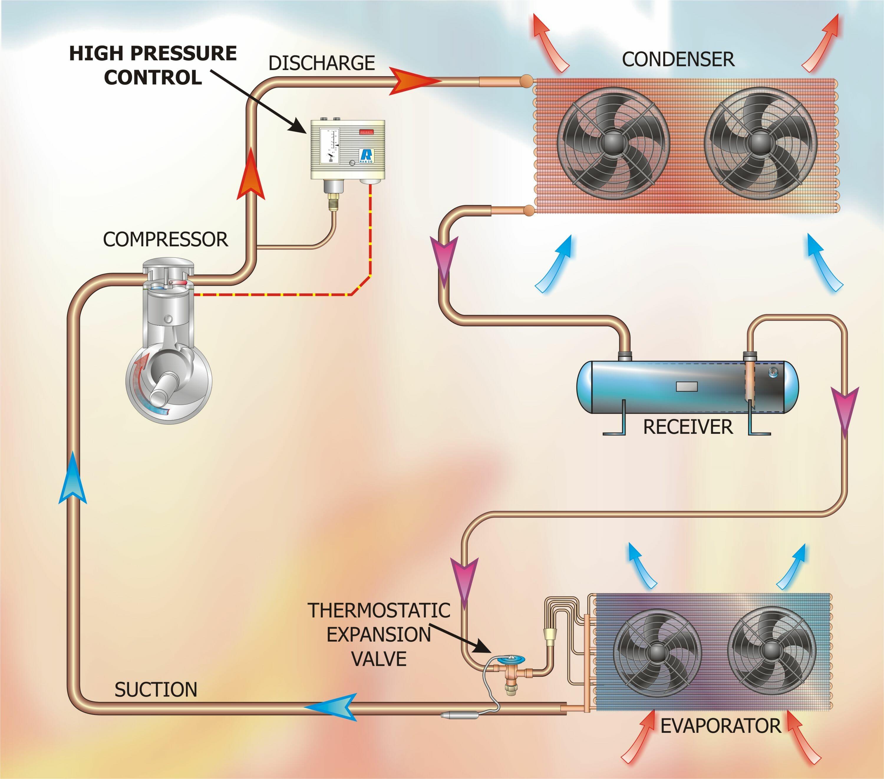
Figure 1 shows the position of a High Pressure Cut-Out Switch sensing compressor discharge pressure on the condenser side of the compressor being used as a high pressure protection limit control.
Figure 1
The operating ranges and differential ranges for High Pressure Cut-Out’s are shown in Table 1 of Part 22 and operate up to 30 bar (440 psi) with a differential of 3.2 to 8 bar (47 to 118 psi).
Figure 2 shows separate High and Low Pressure Cut-Out’s fitted to a refrigeration circuit. In this case the LP Cut-Out is being used for control whilst the HP Cut-Out is being used for protection. A multiple evaporator system has been used in this illustration.
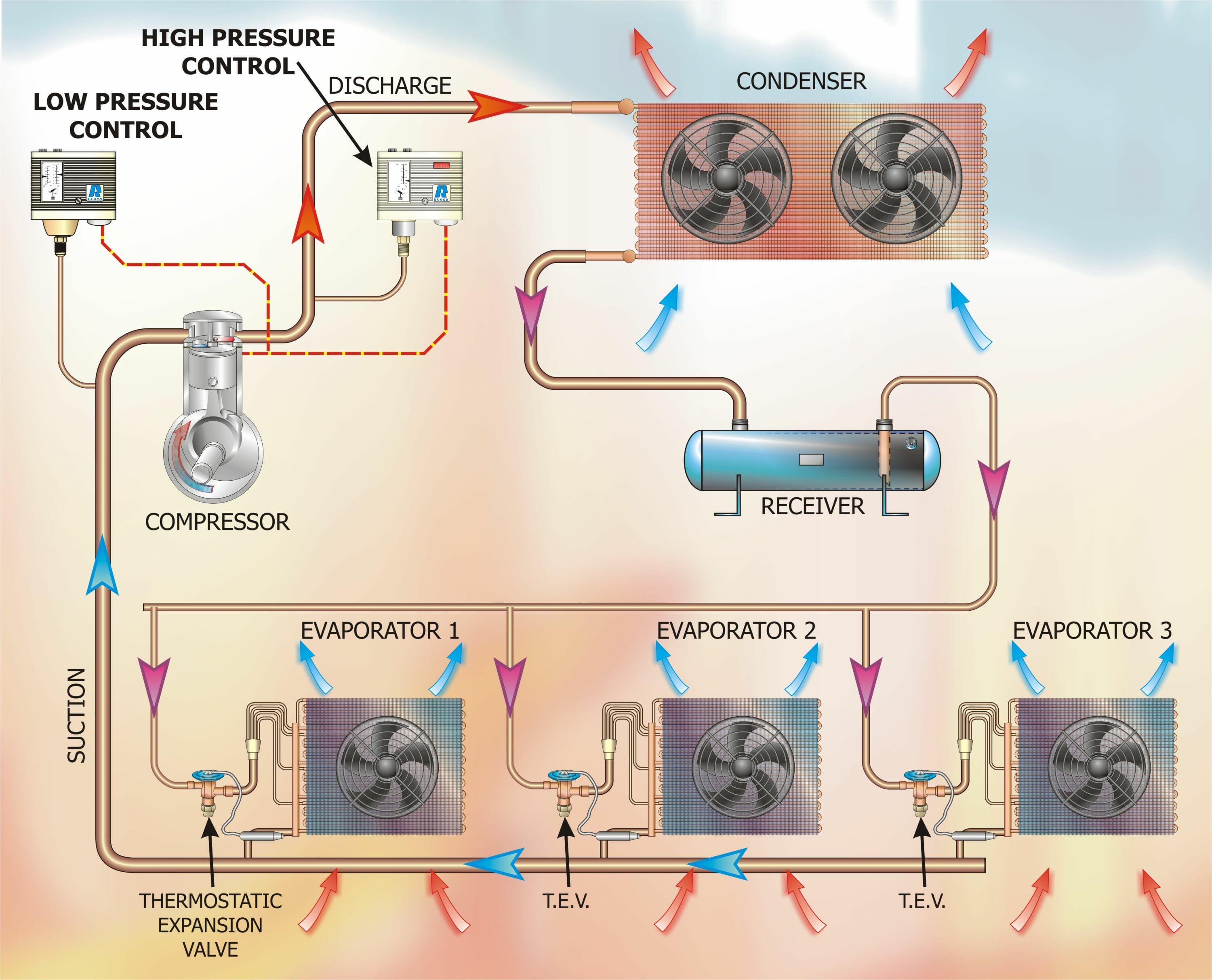
Figure 2 – Low Pressure Control with High Pressure limit
Low & High Pressure Switch – Combined
It is sometimes desirable to have both the Low and High Pressure Cut-Out Switches located in one housing. This eliminates labour associated with mounting the device.
Illustrations of this combined type of switch are shown in Figure 3.
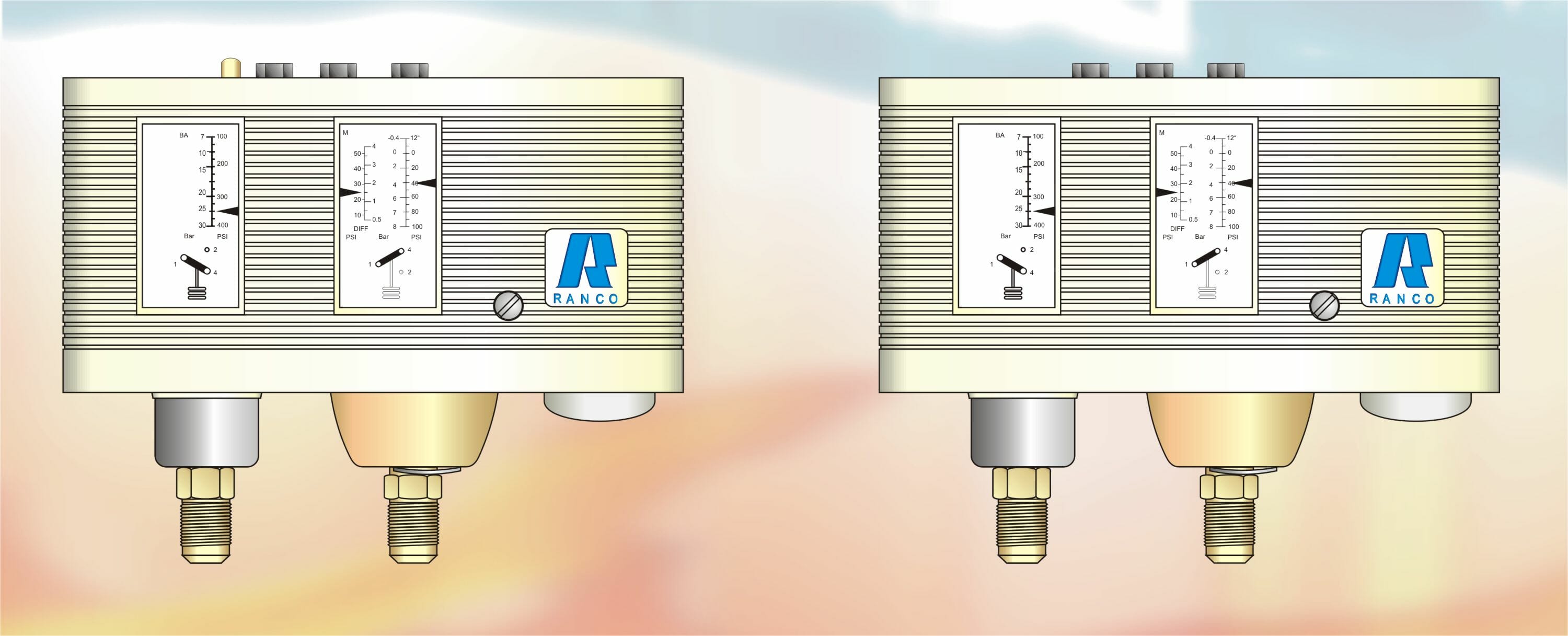
Figure 3
Whilst the two switches shown appear identical, there are some subtle differences. These are listed below with some of the key features.
- Ammonia and TUV options
- Option of Assurance against rising and falling pressure
- Stainless steel bellows to suit high pressure systems / refrigerants
- Dual Signal Switch with independent High & Low Pressure operation
OR
- SPDT Switch (Single Pole-Double Throw)
- IP44 Enclosure Rating
- Various combinations of auto or manual reset on HP & LP functions
Another use for this arrangement is in the form of a Dual Pressure Control.
In order that the system can be cycled with the LP control and in the event of excess high pressure due to say a blockage in the condenser, the HP control would shut down the system. This can be achieved using a dual pressure control [Figure 4] with exactly the same result.
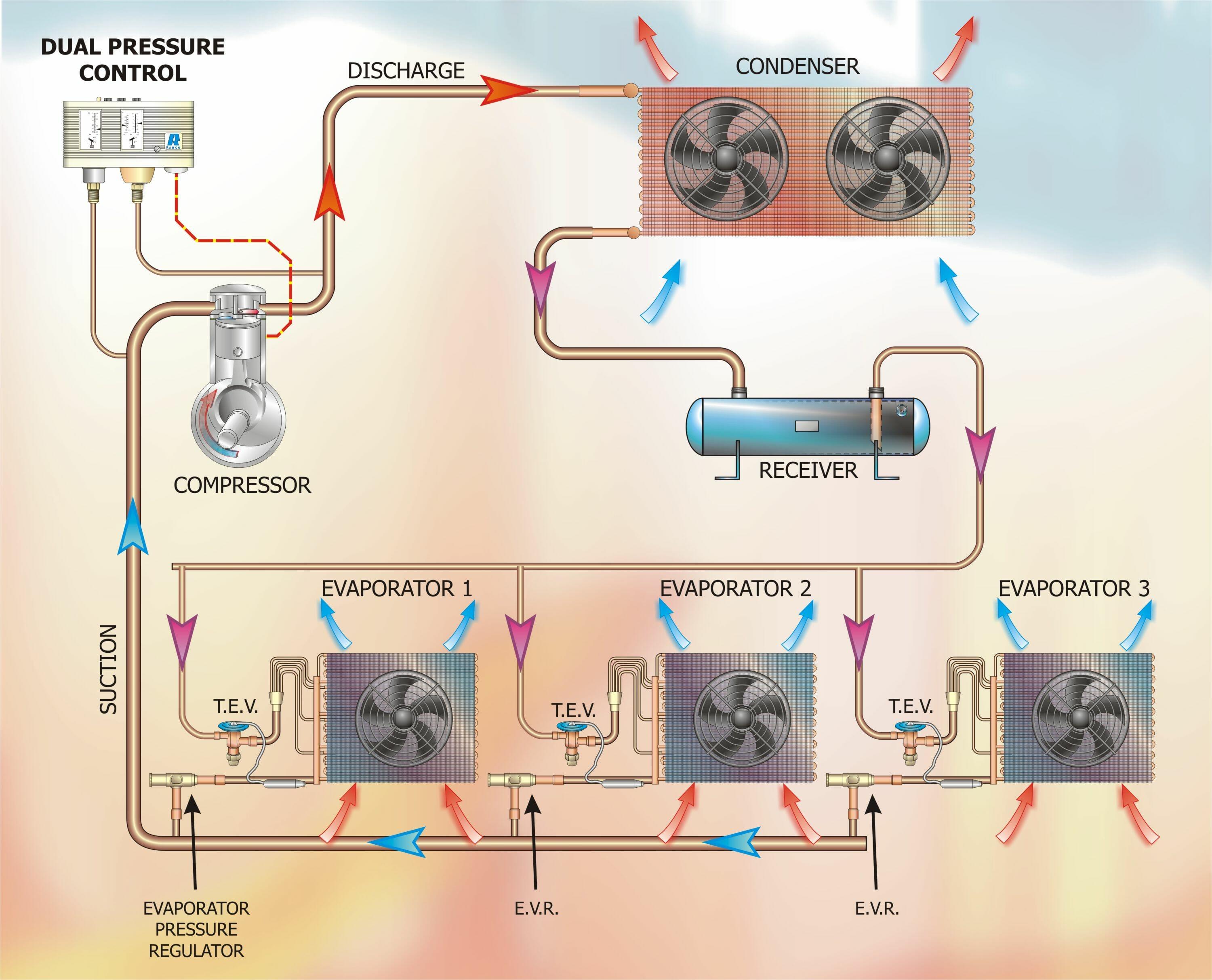
Figure 4 – Dual Pressure Control
Auto-Reset & Manual Reset
Low Pressure Cut-Out – Auto-Reset
It is normal for the Low Pressure Cut-Out to be configured for Auto Reset. This allows the LP Cut-Out to automatically reset after a cold start has caused it to nuisance trip as described earlier.
If there is a refrigerant leak and the low side pressure falls below the setpoint of the LP Cut-Out, the compressor will be stopped and cannot restart until the system is repaired and recharged, thus bringing the standing and operating pressures up to a level in excess of the setpoint. The system compressor(s) cannot therefore start and draw in air and moisture.
In the event of the application or system being critical for one reason or another, it may be that the designer will want to install a manual reset LP Cut-Out. These have been applied to micro-processor driven applications where additional protection has been added to that offered by the controller and software routines.
High Pressure Cut-Out – Manual Reset
Should the High Pressure Cut-Out operate, it must always be assumed that the system has attempted to exceeded the safe Allowable Pressure and that this situation might repeat itself if the system were allowed to attempt another start. It is for this reason that the HP Cut-Out is normally always configured to trip and shut down the compressor(s) indefinitely. This forces the user or system owner to notice that refrigeration is no longer being provided and a refrigeration engineer is then summoned to investigate the problem. As you know, a “real refrigeration engineer” will diagnose that the High Pressure Cut-Out has been activated and will then determine the cause of the problem rather simply than resetting the switch!
There are applications for Auto-Reset High Pressure Cut-Outs. These have been used on special applications by our company, Advanced Refrigeration Technology Ltd.
However, a common application of the Auto-Reset HP Cut-Out is that of Low Ambient Control.
NEXT MONTH: Volume 24 – Control, Safety & Protection Devices used in the Vapour Compression Cycle continued.
DISCLAIMER: Whilst every effort is made to ensure absolute accuracy, Business Edge Ltd will not accept any responsibility or liability for direct or indirect losses arising from the use of the data contained in this series of articles.
