 Cassette Split Systems
 Safety Gloves
 UV Leak Detection
 Condensate Drain Pipe
 Nitrogen Regulators
 Filter Driers
 Filter Cores for Core Shells
Vol 21 – Discharge Pipe from Relief Devices
Author Mike Creamer, Business Edge Ltd
AIR CONDITIONING TECHNOLOGY
Volume 21
In last month’s volume 20 we considered the containment of refrigerant in vessels and refrigerant lines coupled with safety and the various methods to meet these requirements. This month we continue with this subject.
Discharge Piping from Relief Devices
The discharge of toxic refrigerants or large quantities of non-toxic refrigerants through Relief Devices must be vented to the outside atmosphere or in the case of Ammonia into a tank of water.
While the Relief Device is discharging, back pressure will build up in the discharge piping which may prevent the device from performing properly or from discharging its rated capacity. For Relief Devices with fixed openings, such as Fusible Plugs and Rupture Members, this back pressure can build up to approximately 50% of the pressure in the Vessel without effecting the capacity of the Relief Device. This is due to the phenomenon known as “critical flow” through a fixed orifice, whereby a decrease in outlet pressure below 50% of the inlet pressure is not accompanied by an increase in flow.
This condition does not necessarily apply to Pressure Relief Valves since the effective opening through a Relief Valve depends on both the orifice diameter and the lift of the valve piston; which in turn depends on the pressure difference across the valve. The amount of back pressure permitted without the loss of capacity through a Pressure Relief Valve will vary depending on the design. In most cases it is considerably less than 50% of the inlet pressure.
For the purpose of establishing some limit, the ANSI/ASHRAE 15 Code permits a Maximum Back Pressure through the discharge piping of 25% of the inlet pressure while the device is discharging at rated capacity. Knowing the Set Pressure and Capacity of the Relief Device, the length of discharge piping for each pipe size can be calculated from the code formula:
9 P2 d5
L = ¾¾¾
C2
where
L = Length of discharge pipe or tube in feet (m)
P = 0.25 [(set pressure x 1.1) + 14.7]
d = Internal diameter of pipe or tube in inches (mm)
C = Minimum required discharge capacity in lbs. of air per minute (kg/s).
Since this calculation is long and complicated, the results have been published in the form of tables in the code.
It is good safety practice to keep the lengths of Discharge Piping well within that permitted by the code. This is particularly important for Relief Valves, since excessive lengths may not only reduce capacity but can cause piston chatter and valve damage while discharging.
PRESSURE RELIEF VALVES
Direct Spring Loaded Type
The most popular type of Relief Valve is the Direct Spring loaded “pop” type. In this type the piston generally contains a synthetic seat disc which seals against the valve seat by means of a spring and adjustable gland. At the Relief Valve setting, the force exerted by the spring is equal to the force exerted by the refrigerant pressure. As the pressure increases above the setting, the Relief Valve will begin to seep until there is enough flow to pop the piston open and provide full discharge. The pressure above the setting at which the piston is fully open depends on the Relief Valve design. Since the flow rate is measured at a pressure of 10% above the setting, it is necessary that the Relief Valve open within this 10%.
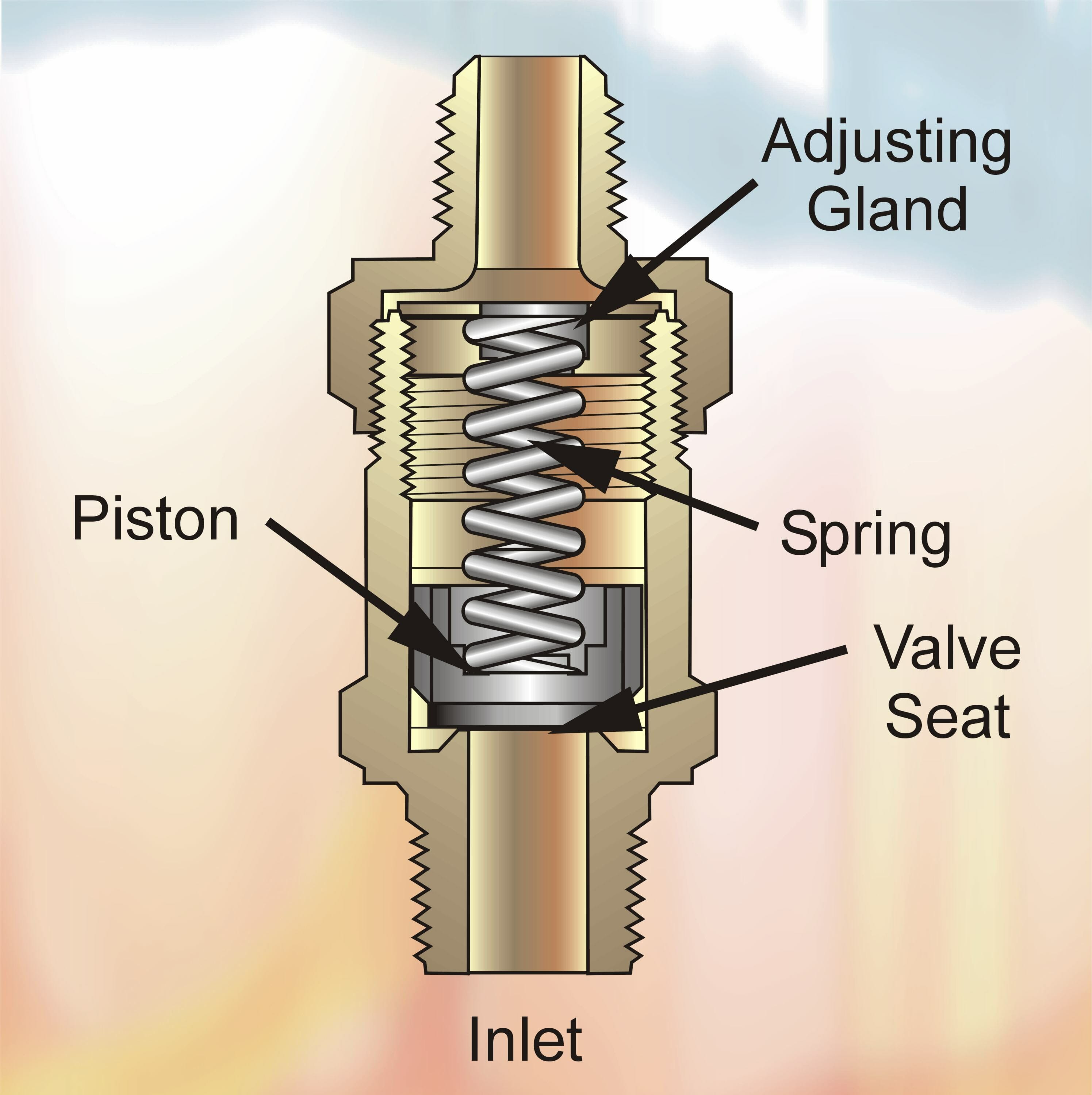
FIG 1
This type of Relief Valve operates on a Fixed Pressure differential from inlet to outlet. It is affected by Back Pressure so that it is not permissible to install a Rupture Member at the Relief Valve outlet. The ANSI/ASHRAE 15 Code does permit a Rupture Member to be installed between the Pressure Vessel and the Relief Valve inlet. The space between the Rupture Member and Relief Valve must be equipped with a Pressure Gauge or Vent to indicate whether the Rupture Member has leaked or burst. If Back Pressure is allowed to build up in this space, the Rupture Member will not burst at its design pressure.
The advantages of the “pop” type Relief Valve are: simplicity of design, low initial cost and high discharge capacity.
Reseating After Discharging
Relief Valves are designed to reclose automatically at a predetermined pressure after they have discharged. The difference between the Set Pressure and the Reclosing Pressure is called the “Blowdown”. The Amount of “Blowdown” will vary with the Relief Valve design and for most “pop” type valves will be between 20% to 30% below the set pressure. Reseating should occur within 5% to 10% below the Reclosing Pressure. Failure to reseat tightly is generally due to an accumulation of dirt and foreign material on the Relief Valve seat disc which occurs while the Relief Valve is discharging. Since Filters or Screens are not permitted to be installed ahead of Relief Valves, for obvious safety reasons, this condition is likely to occur whenever dirt and foreign material are present in the system. For this reason it is almost impossible to predict, with any degree of certainty, the reliability of Relief Valves resealing after they have discharged in service.
Diaphragm Type
The Diaphragm (or bellows) type of Relief Valve is indirectly spring loaded whereby the system pressure acts upon a diaphragm which lifts the piston from the Relief Valve seat. Since the external area of the diaphragm is exposed to atmospheric pressure, the Relief Valve setting is not appreciably affected by Back Pressure. This makes the Diaphragm Type particularly suitable for high side to low discharge in a refrigeration system. As the low side pressure increases, the Relief Valve setting will decease slightly so that it will open at a pressure lower than the stamped pressure setting. The amount of decrease depends on the ratio of the seat area to the diaphragm area. For this same reason the discharge capacity will actually increase up to a certain point with increasing Back Pressure.
The disadvantages of the Diaphragm Relief Valve are its high initial cost and relatively low capacity. It has the advantage of permitting the use of a Rupture Member to be installed in series at the Relief Valve outlet to provide a dual seal. This can be done without affecting the safety of the installation and without the need for a Pressure Gauge or Vent between the Relief Valve and Rupture Member.
Use of Three-way Valves
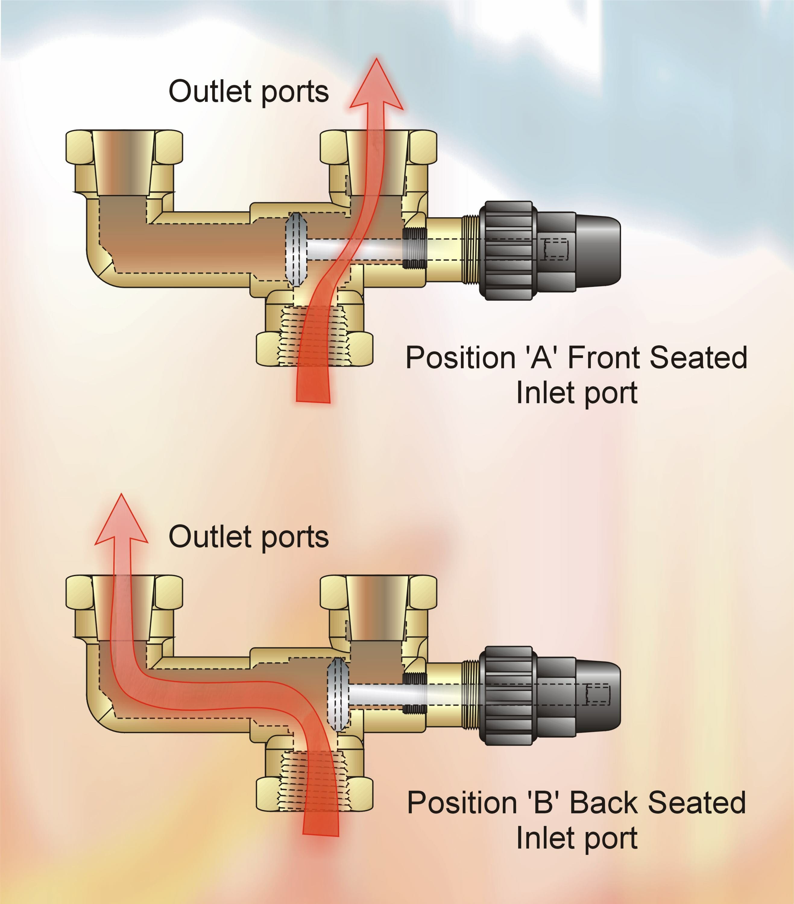
FIG 2
The Dual Relief Valve installation consists of one Three-way Shut-Off Valve and two Relief Valves. The design of the Three-way Valve insures that both Relief Valves cannot be shut off from the protected Pressure Vessel at the same time. This permits safe removal of either Relief Valve for repair or replacement, while the Vessel is protected and under pressure.
The use of a Three-way Valve with two Relief Devices, which meets the code requirements for Vessels 10 cubic feet or more gross volume, is recommended for any installation containing a large quantity of expensive refrigerants.
If two Relief Valves are used, the Three-way Valve should be tested so that full system pressure is applied to both Relief Valves. After checking for leaks, the Three-way Valve should be closed to one position so that only one Relief Valve is exposed to the variable system pressure.
The Three-way Valve arrangement with two Relief Devices permits periodic checking and replacement when necessary, of either Relief Device while the system is operating. This can be accomplished without the need to blow the Refrigerant Charge.
Factors to Consider When Installing Relief Valves
- Provide a pressure vessel which will permit the relief valve to be set at least 25% above the maximum system pressure.
- Select a relief valve having sufficient capacity for code requirements.
- Select a relief valve suitable for the type of refrigerant used.
- Use the proper size and length of discharge tube or pipe.
- Do not discharge the relief valve prior to installation or when pressure testing the system.
- For systems containing large quantities of refrigerant, use a three-way valve and two relief valves.
DISCLAIMER: Whilst every effort is made to ensure absolute accuracy, Business Edge Ltd will not accept any responsibility or liability for direct or indirect losses arising from the use of the data contained in this series of articles.
