 Cassette Split Systems
 Safety Gloves
 UV Leak Detection
 Condensate Drain Pipe
 Nitrogen Regulators
 Filter Driers
 Filter Cores for Core Shells
Vol 20 – Pressure Relief & Safety Devices
Author Mike Creamer, Business Edge Ltd
AIR CONDITIONING TECHNOLOGY
Volume 20
PRESSURE RELIEF & SAFETY DEVICES
Last month’s volume 19 covered liquid refrigerant receivers. The containment of refrigerant in vessels and refrigerant lines demands that safety be given due consideration to eliminate risk to persons due to refrigerant release or explosion and to minimise refrigerant losses thereby avoiding environmental damage and financial loss associated with replacement. This month we review various methods to meet the aforementioned requirements.
SAFETY RELIEF DEVICES for REFRIGERANT PRESSURE VESSELS – WHY A RELIEF DEVICE IS NECESSARY
A Refrigerant Safety Relief Device is designed to prevent pressure in a Vessel from rising above a safe limit when operating controls fail or when the Vessel is exposed to excessive heat.
When a Vessel, containing liquid refrigerant, is shut off from other parts of the system a rise in temperature will cause a rise in pressure. If the Vessel is completely filled with liquid a small rise in temperature will cause a rapid and excessive rise in pressure due to the expansion of the liquid. If the Vessel contains both liquid and vapour, which is normal for Refrigerant Receivers, the pressure will rise according to the temperature-pressure saturation characteristics of the refrigerant.
If the density of the liquid vapour mixture in the Vessel exceeds the critical density of the refrigerant, an increase in temperature will cause an increase the percentage of liquid in the Vessel until the Vessel is completely filled with liquid. A small increase in temperature beyond this point will result in a rapid and excessive rise in pressure. This condition can occur at temperatures well below the critical temperature of the refrigerant as a result of the exposure of the Vessel to excessive heat as in the case of Fire.
If pressure builds up high enough to cause the Vessel to rupture, large quantities of liquid refrigerant will then be released. This causes a sudden reduction of pressure so that the liquid released is vaporised almost instantly with explosive results.
With a suitable Relief Device installed on the Vessel, the refrigerant is released at a controlled rate and a safe pressure is maintained in the Vessel.
TYPES OF RELIEF DEVICES
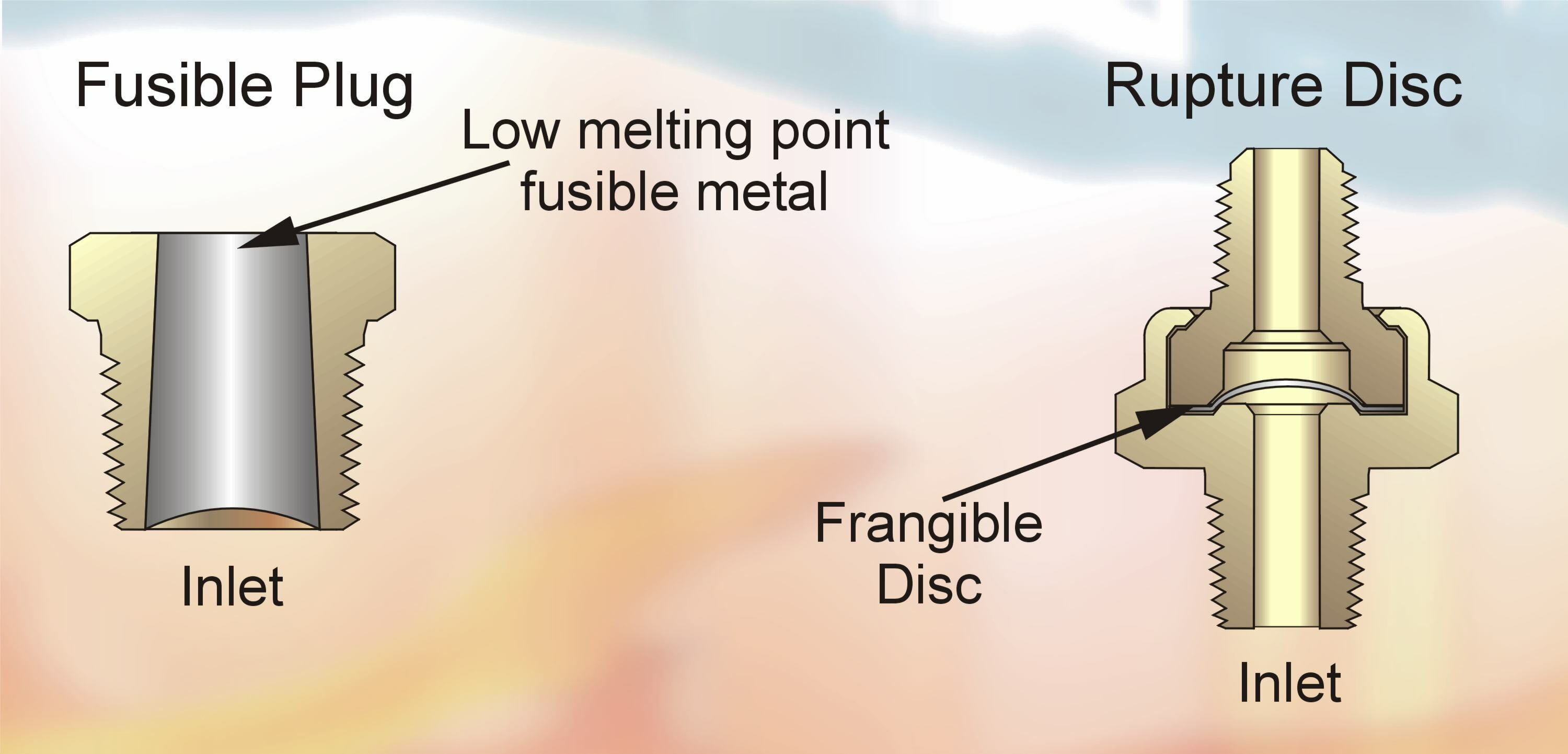
There are three general types of Relief Devices commonly used, namely: the Fusible Plug, the Rupture Member and the Pressure Relief Valve.
The Fusible Plug contains a fusible member which melts at a predetermined temperature corresponding to the safe saturation pressure of the refrigerant.
The Rupture Member contains a frangible disc designed to rupture at a predetermined pressure.
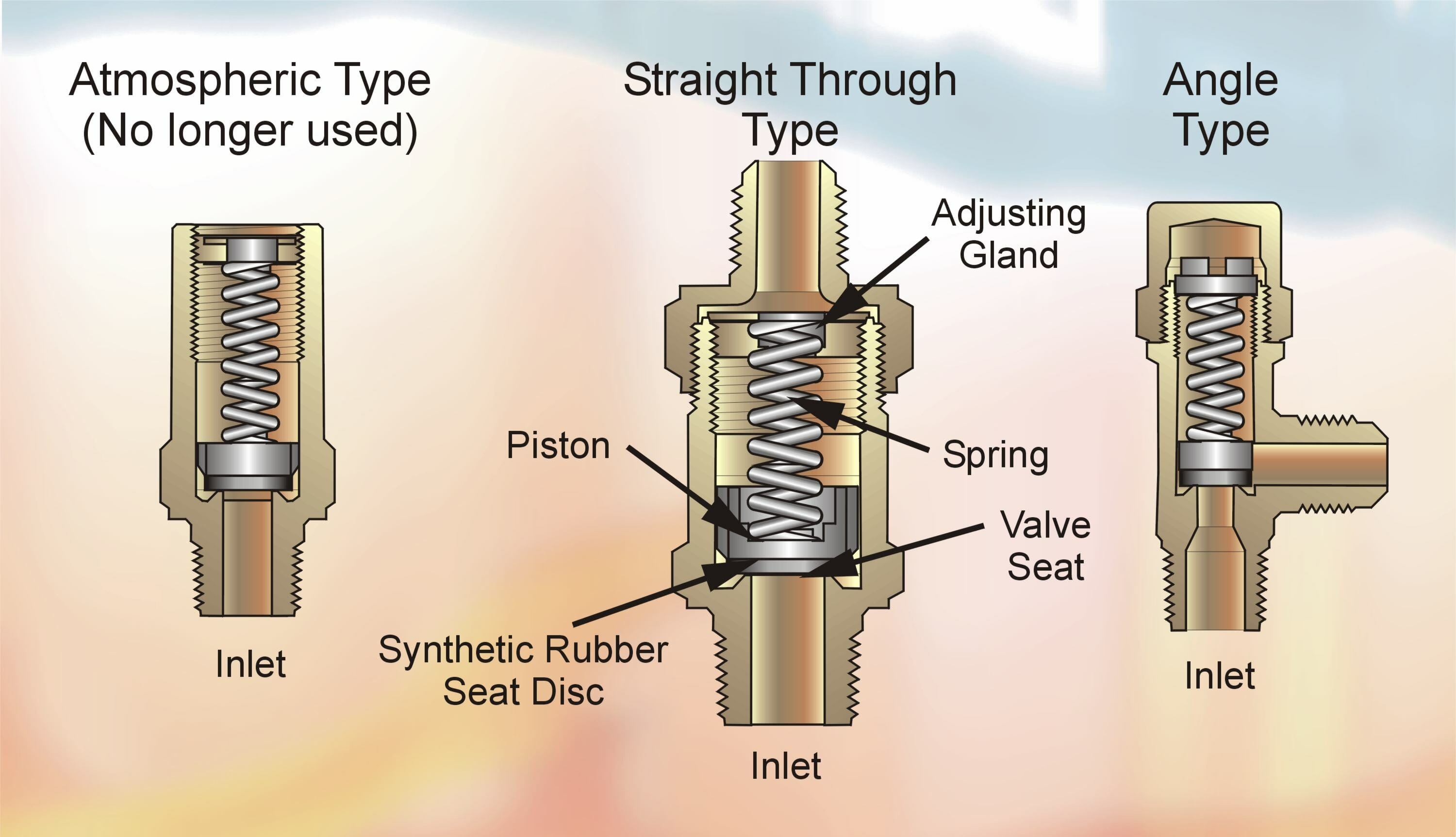
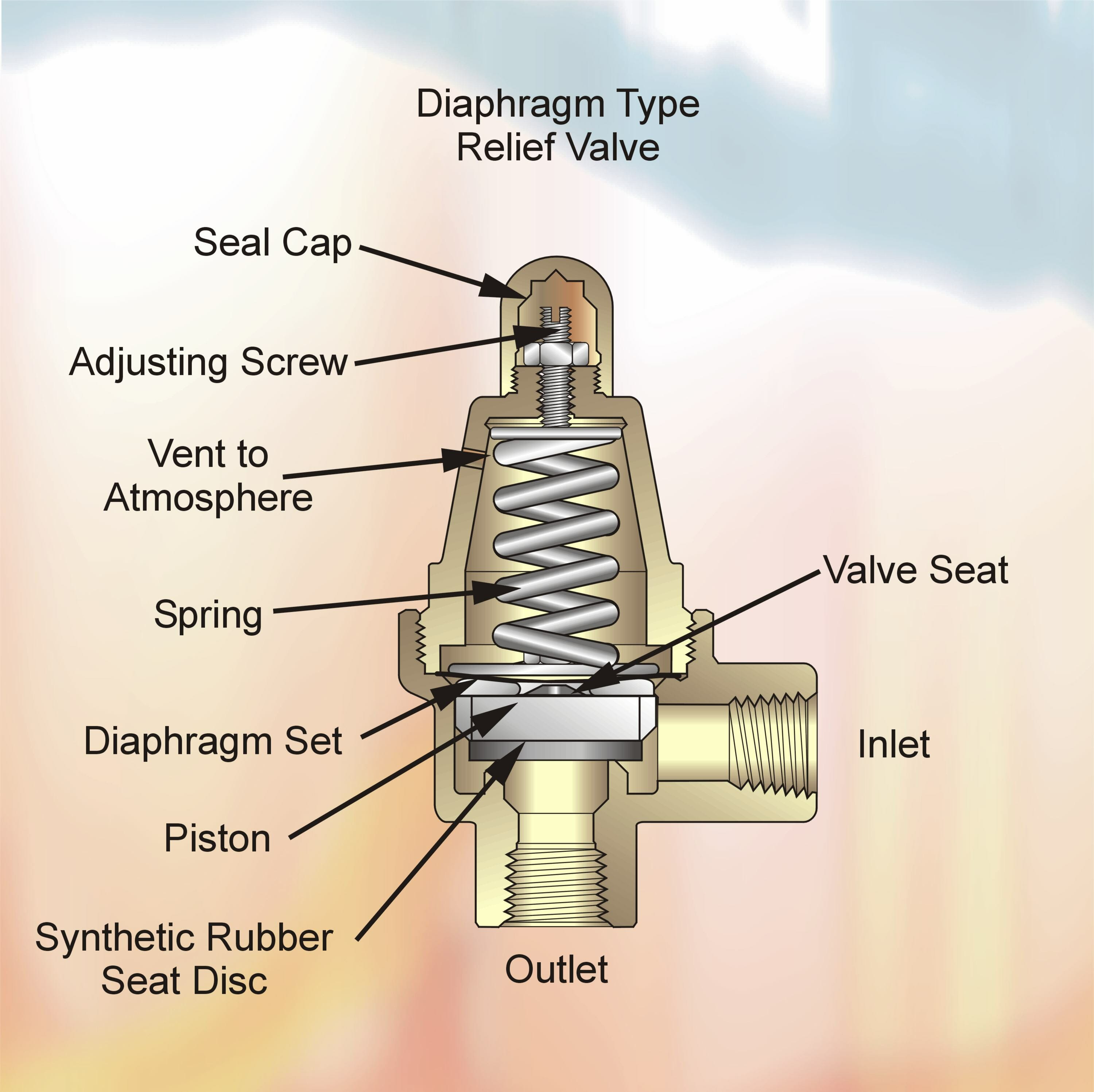
The Pressure Relief Valve is a pressure actuated valve held closed by a spring or other means and designed to automatically relieve at a predetermined pressure.
NEIL FIGURES 1 – 3 APPLY HERE ALTHOUGH YOU MAY WISH TO SPRINKLE THEM THROUGHOUT THE ARTICLE (1 & 3 CAN BE GROUPED TOGETHER WITH 2 LOCATED ELSEWHERE)
RELIEF DEVICE SELECTION
Four Requirements to Select the Correct Relief Device
- Type of Refrigerant
- Size of Vessel. This determines type of Relief Device which can be used and the discharge capacity requirement of the relief valve.
- Design Pressure of Vessel to be protected.This determines the pressure setting of the Relief Device.
- Length of discharge piping required from outlet of the Relief Valve.Correct size required to prevent back pressure from building up in the discharge piping, and preventing the Relief Valve from discharging at its rated capacity.
ANSI/ASHRAE 15 CODE REQUIREMENTS FOR RELIEF DEVICES
Selection of Types
- Pressure Vessels with internal gross volume of 3 cubic feet or less containing liquid refrigerant, which may be shut off by valves from all other parts of a refrigerant system, shall be protected by a Pressure-Relief Device or Fusible Plug.
- Pressure Vessels of less than 6 inches inside diameter can be protected by a Pressure-Relief Device or a Fusible Plug from Fire or other abnormal conditions.
- Pressure Vessels over 3 cubic feet but less than 10 cubic feet internal gross volume may use a single Pressure-Relief Valve or Rupture Member (but not a Fusible Plug).
- Pressure Vessels of 10 cubic feet internal-gross volume or more require a Three-way Valve and two Parallel Relief Valves. Each Relief Valve shall have sufficient capacity to protect the Vessel, because only one Relief Valve shall be under system pressure at a time.
- No Stop Valve may be located between the Vessel and any Relief Device except the Three-way type with two Relief Valves permitting only one Relief Valve to be shut off at a time.
Discharge Capacity
The ANSI/ASHRAE 15 Code provides a formula for calculating the required discharge capacity of the Relief Device:
C = IDL
Where
C = Minimum required discharge capacity of the Relief Device in lbs. of air per minute (kg/s)
D = Outside diameter of the Vessel in feet (m)
L = Length of the Vessel in feet (m)
f = Factor dependent upon type of refrigerant.
Refrigerant Value of f
When used on the low side of a limited-charge cascade system:
R-170, R-744, R-1150 1.0 (0.082)
R-13, R-13B1, R-503 2.0 (0.163)
R-14 2.5 (0.203)
Other applications:
R-717 0.5 (0.041)
R-11, R-40, R-113, R-123, R-142b,
R-152a, R-290, R-600, R-600a, R-611,
R-764 1.0 (0.082)
R-12, R-22, R-114, R-134a, R-C318,
R-500, R-1270 1.6 (0.131)
R-115, R-502 2.5 (0.203)
We recommend that the latest edition of ANSI/ASHRAE 15 be consulted for other refrigerants.
This formula was based on a Fire condition and developed by assuming a flame temperature to calculate the BTU heat input radiated to the Vessel. As pressure rises in the Vessel, the discharging Relief Device acts as an expansion valve to provide a cooling effect. Since the latent heat of vaporisation of the refrigerant is known, it is made equal to the heat input from the Fire to determine the amount of refrigerant which must be discharged to maintain uniform temperature and pressure in the Vessel..
Since the heat input depends on the size of the Vessel exposed to the Fire, the diameter “D” and length “L” of the Vessel become part of the formula. The factor “f” provides for the difference in latent heats of the various refrigerants and converts the flow of refrigerant to the equivalent flow of air. This permits the rating of Relief Devices to be expressed in terms of discharge of air in lbs. per minute regardless of the type of refrigerant used.
For example a Pressure Vessel 1 foot in diameter by 5 feet long containing Refrigerant 22
(f = 1.6) would require the Relief Device to discharge: 1.6 x 1 x 5 = 8 lbs. of air per minute. For Ammonia (f = 0.5) this would amount to only 0.5 x 1 x 5 = 2.5 lbs. of air per minute.
This smaller capacity requirement for Ammonia is due to its high latent heat of vaporisation with greater cooling effect. Capacities of Pressure Relief Valves are determined by test in accordance with the provisions of the ASME Boiler and Pressure Vessel Code, Section VIII, Div. 1 Relief Valves, approved by the National Board of Boiler and Pressure Vessel Inspectors, and are stamped with the code symbol. This symbol consists of the letters “UV” in a clover leaf design with the letters “NB” stamped directly below the symbol. In addition, the pressure setting and capacity are stamped on the Relief Valve.
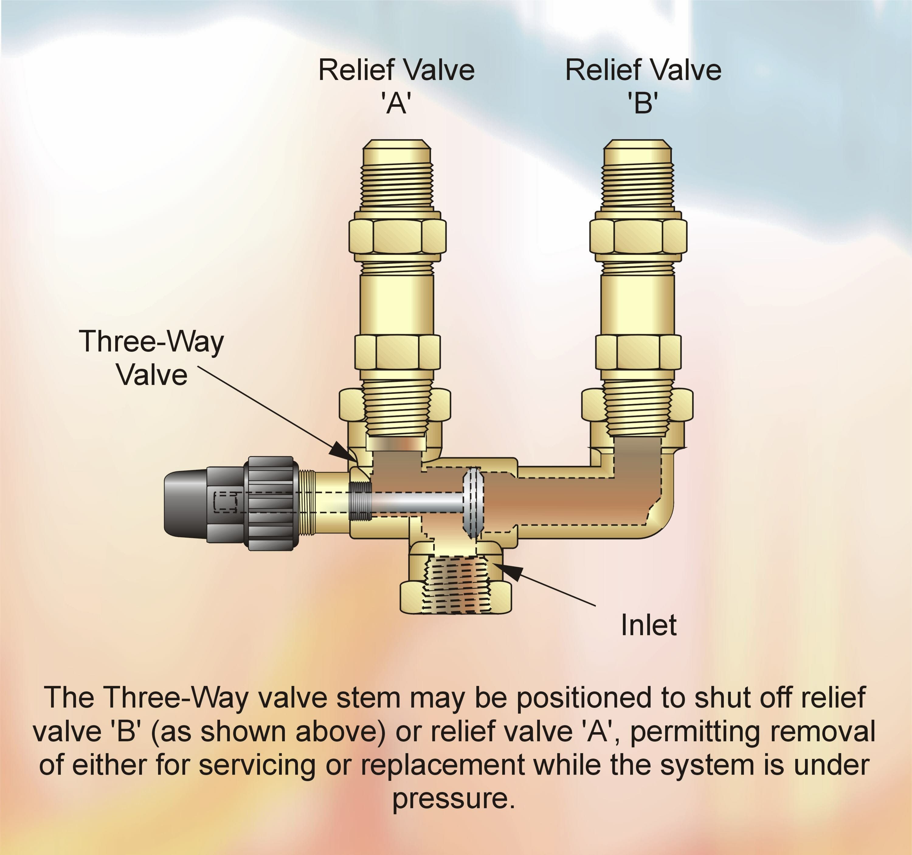
FIG 4
Capacities of Fusible Plugs and Rupture Members, if not stamped by the manufacturer, may be determined by the following code formula:
C = 0.8 P,d2
where
C = Rated Discharge Capacity in lbs. of air per minute (kg/s)
d = Internal diameter of bore of Fusible Plug or Rupture Member in inches.
For Rupture Members:
P1 = 1.10 x set pressure PSIG (kPa Gage) + 14.7.
For Fusible Plugs:
P1 = Absolute saturation pressure corresponding to the stamped
temperature melting point of the Fusible Plug or the critical pressure of the refrigerant used, whichever is smaller, PSIA (kPa)
The capacity of a Relief Device will increase proportionately with an increase in pressure setting. Therefore, the capacity stamped on the Relief Device by the manufacturer is correct only for the pressure setting stamped on the device. The ANSI/ASHRAE 15 Code formula for determining the required capacity is independent of the pressure setting. To obtain the maximum rated capacity of the Relief Device, the setting should be as high as the design pressure of the Vessel will permit.
Pressure Setting
Pressure Vessels are normally manufactured to a safety factor of 2.5 to 5 so that the Maximum Bursting Pressure is 2.5 to 5 times the rated Design Working Pressure. Important, the Maximum Pressure Setting for a Relief Valve is limited by the Design Working Pressure of the Vessel to be protected. The Relief Device must also have enough discharge capacity to prevent the pressure in the Vessel from rising more than 10% above its Design Pressure. Since the capacity of a Relief Device is measured at 10% above its stamped setting, the setting cannot exceed the Design Pressure of the Vessel.
To prevent loss of refrigerant through Pressure Relief Devices during normal operating conditions, it is necessary that the Relief Device setting be substantially higher than the system Operating Pressure.
Unless specified otherwise by local governing codes, the Relief Valve should be set at a pressure equal to the Design Working Pressure of the Vessel as furnished by the manufacturer and stamped on the Vessel. For proper functioning of the Relief Valve, the Design Pressure of the Vessel and corresponding Relief Valve Setting should be at least 25% higher than the normal Maximum Operating Pressure for the refrigerant used.
This factor of safety will provide sufficient spring force on the valve seat to maintain a tight seal and still allow for setting tolerances and other factors which cause settings to vary. Although Relief Valves are set at the factory within a few pounds of the stamped setting, the variation may be as much as 10% after the Relief Valves have been stored or placed in service for a period of time.
DISCLAIMER: Whilst every effort is made to ensure absolute accuracy, Business Edge Ltd will not accept any responsibility or liability for direct or indirect losses arising from the use of the data contained in this series of articles.
