 Cassette Split Systems
 Safety Gloves
 UV Leak Detection
 Condensate Drain Pipe
 Nitrogen Regulators
 Filter Driers
 Filter Cores for Core Shells
Vol.3 REFRIGERATION CYCLES
Author Mike Creamer, Business Edge Ltd
PART 3
REFRIGERATION CYCLES
In last months article we covered basic thermodynamics, elementary formulae and studied the effects of pressure over water. Figure 1 provides a clear visual understanding of the behaviour of water at a pressure of 1.01325 bar when heat energy is added or removed.
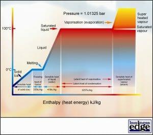
FIGURE 1
It is important to remember the key values for water shown in Figure 1 as these can be used in many calculations for air conditioning and refrigeration design and commissioning work.
Steam Tables
Changes in the pressure above any liquid or vapour affect the temperatures at which a change of state occurs and the amount of heat energy involved. Steam Tables list these different values over a wide range of pressures. Table 1 lists the values for water at a few selected pressures.
TABLE 1
Pressure
Saturation
Temperature Specific
Volume Heat Energy Content
Sens Latent Total
(bar) (Deg C) (m3/kg) (kJ/kg) (kJ/kg) (kJ/kg)
0.006112 0.01 206.1 0.0 2500.8 2500.8
0.006566 1.0 192.6 4.2 2498.3 2502.5
0.01227 10.0 106.4 42.0 2477.2 2519.2
0.02337 20.0 57.84 83.9 2453.7 2537.6
0.04242 30.0 32.93 125.7 2430.0 2555.7
0.07375 40.0 19.55 167.5 2406.2 2573.7
0.1233 50.0 12.04 209.3 2382.1 2591.4
0.1992 60.0 7.678 251.1 2357.9 2609.0
0.3116 70.0 5.045 293.0 2333.3 2626.3
0.4736 80.0 3.408 334.9 2308.3 2643.2
0.7011 90.0 2.361 376.9 2282.8 2659.7
1.01325 100.0 1.673 419.1 2256.7 2675.8
5.0 151.8 0.375 639.0 2562.0 3201.0
10.0 179.9 0.194 762.0 2584.0 3346.0
20.0 212.4 0.099 907.0 2600.0 3507.0
30.0 233.8 0.066 1004.0 2603.0 3607.0
Note the substantial changes that occur in specific volume and the rate of change of pressure in relation to saturation temperature. Observe the substantial amount of latent heat energy transfer involved in the change of state from Saturated Liquid to Saturated Vapour (or from Saturated vapour to Saturated Liquid) and how this changes considerably with pressure. This is far greater than the small amount of sensible heat energy associated with a change in temperature alone. Clearly, a cooling system for air conditioning or refrigeration using a circulating fluid would be most effective if the latent heat energy transfer can be harnessed through a change of state.
The Vapour Compression Cycle and Absorption Cycle use this characteristic very effectively. The Double Effect Absorption Cycle actually uses water as the Refrigerant. The Single Effect Absorption Cycle uses ammonia as the Refrigerant. A Refrigerant can be defined as a reticulating fluid transferring heat energy from one part of the system to another.
The Vapour Compression Cycle uses a wide range of Refrigerants according to application requirements including operating temperatures, pressures, ambient temperatures and efficiency.
Compare the characteristics of Refrigerant R22 (Chlorodifluoromethane) in Table 2 with those of water in Table 1.
TABLE 2
Pressure Saturation
Temperature Liquid
Volume Vapour
Volume Heat Energy Content
Liquid Latent Vapour
(bar) (Deg C) m3/Mg m3/kg (kJ/kg) (kJ/kg) (kJ/kg)
1.05161 -40.0 0.70924 0.20587 55.98 232.61 288.59
1.63466 -30.0 0.72420 0.136244 66.62 226.67 293.30
2.44438 -20.0 0.75046 0.093268 77.50 220.30 297.80
3.53431 -10.0 0.75822 0.065692 88.62 213.43 302.05
4.96256 0.0 0.77778 0.047389 100.00 205.99 305.99
5.82289 5.0 0.78834 0.040561 105.79 202.02 307.82
6.79153 10.0 0.79949 0.034873 111.66 197.88 309.55
7.87684 15.0 0.81131 0.030105 117.61 193.55 311.17
9.08749 20.0 0.82387 0.026084 123.65 189.01 312.67
Pressure – Enthalpy Diagram
The figures in Table 2 have been taken from Tables of Refrigerant Properties, which fully define all the thermodynamic characteristics of refrigerant R22. The detailed operating characteristics of a working vapour compression system can be plotted on this diagram.
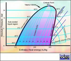
FIGURE 2
The Vapour Compression Cycle
The primary purpose of an air conditioning or refrigeration system is to remove heat energy at a low temperature from a conditioned space or body and transfer (reject) this heat energy into another medium at a higher temperature. Heat energy may be rejected into air, water or soil.
This process is very often continuous since heat energy will always continue to flow from higher temperature surroundings into the conditioned space being maintained at lower temperature. Insulation plays a major part in minimising this heat energy flow in low temperature applications.
Air Conditioning & Refrigeration Heat Load
Heat energy flow from higher temperature surroundings through the fabric of the conditioned space are termed Transmission or Conducted gains. There are many other sources of heat gain to the conditioned space and these include heat energy from:
* Solar radiation energy striking the surfaces of the building or cold store (Sensible)
* Warm, moist air entering the conditioned space through infiltration or ventilation (Sensible & Latent)
* Products or processes (Sensible and Latent)
* Lighting, motors, machinery and computers (Sensible)
* Occupants (Sensible and Latent)
These are carefully calculated and the total is popularly known as the Heat Load or Cooling Load. The Heat Load normally comprises Sensible Heat and Latent Heat and the air conditioning or refrigeration system must be capable of removing these continuously. The sum of Sensible and Latent Heat energy is known as Total Heat or Total Enthalpy. Air conditioning and refrigeration loads will be discussed later in the series.
The Evaporator
Since the capacity of a refrigerant to absorb heat energy is greatest when changing state from liquid to vapour, the heat exchanger (Evaporator) within the conditioned space is continuously supplied with liquid refrigerant, which vaporises in order to absorb heat energy from the conditioned space. Air is used to transport sensible and latent heat energy from products, lights, machinery and occupants to the Evaporator. In order for this to be effective and efficient, an Evaporator Fan is used to pass return air over the Evaporator Coil and to distribute conditioned air throughout the space. See Figure 3.
If liquid refrigerant R22 is allowed to vapourise at a pressure of 1.01325 bar, the Saturation Temperature (or Evaporating Temperature) will be -40.8 Deg C. As the refrigerant vaporises, heat energy is absorbed and is termed Latent Heat of Vaporisation. The Latent Heat of Vaporisation (approximately 140 kJ/kg) required to vaporise the liquid is taken from the conditioned space thus providing cooling. The heat energy from the space is transferred to the vapour.
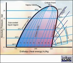
FIGURE 3
However, in order to maintain the conditioned space at a suitable temperature for comfort air conditioning (22 Deg C), it is not necessary for the refrigerant to change state at such a low temperature (Evaporating Temperature). The design of the evaporator and the amount of airflow will determine what Evaporating Temperature is required for a given leaving air temperature from the evaporator coil. If an Evaporating Temperature of 5 Deg C were required, it will be necessary to raise the Evaporating Pressure to 5 bar. See Figure 4.
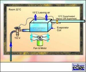
FIGURE 4
Superheat
Note that some of the heat energy from the room is also raising the temperature of the refrigerant above the Saturation Temperature within the Evaporator. This Superheating of the refrigerant is essential to protect the compressor from taking in liquid refrigerant, which would otherwise result in mechanical damage and failure. However, as superheating the vapour does not absorb much heat energy from the conditioned space and also makes poor use of the evaporator, it should be maintained at a minimum level of 5.0 – 7.0 K.
The process taking place within the Evaporator is shown on the P-E Diagram in Figure 5. The amount of energy absorbed by the refrigerant during vaporisation is 167 kJ/kg (Latent Heat of Vaporisation) and a further 3 kJ/kg has been absorbed during Superheating of the vapour. The total of these (170 kJ/kg) is equal to the amount of cooling performed in the Evaporator (and the space) and is termed the Net Refrigerating Effect.
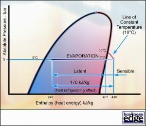
FIGURE 5
The Compressor
The Superheated refrigerant vapour leaving the Evaporator must be recycled and returned to liquid form for use at the Evaporator. In order for the refrigerant to be returned to a liquid state it is necessary to remove heat energy by bringing the refrigerant into contact with a medium (sink) at a lower temperature. If the system is to reject this heat energy to outdoor air during peak summer conditions where the air temperature may be as high as 30 Deg C, the Saturation Temperature of the refrigerant must be raised from 5 Deg C to a higher temperature than 30 Deg C, say 40 Deg C. This is achieved by raising the pressure of the Saturated Vapour leaving the Evaporator by passing the vapour through a Compressor. This higher Saturation Temperature is known as the Condensing Temperature. See Figure 6.
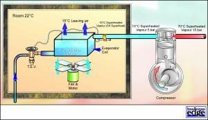
FIGURE 6
The process taking place within the Compressor is shown on the P-E Diagram in Figure 7. Note that the compression process follows the lines of Constant Entropy. The refrigerant has taken up 23 kJ/kg of energy during this process and this is termed the Heat of Compression. The resulting leaving temperature is now much higher than the entering temperature (70 Deg C) and the Condensing Pressure has been raised to 15 bar.
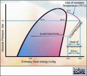
FIGURE 7
The Condenser
The Condenser must remove heat energy from the refrigerant and reject this to a lower temperature medium (sink), usually outdoor (Ambient) air. Assuming an Ambient Temperature of 30 Deg C and a Condensing Temperature of 40 Deg C, a temperature difference of 10 K exists. This is often known as the Approach Temperature. See Figure 8.
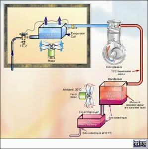
FIGURE 8
Total Heat of Rejection
The energy that must be rejected by the Condenser comprises the heat energy removed by each kilogram of refrigerant passing through the Evaporator (170 kJ/kg) and the heat energy added to each kilogram of refrigerant passing through the Compressor (23 kJ/kg). The total heat that must be rejected therefore equals 193 kJ/kg and is termed the Total Heat of Rejection (THR). The Condenser coil is therefore normally larger than the Evaporator coil.
The gas leaving the Compressor and entering the Condenser is considerably superheated. The Condenser must therefore Desuperheat the refrigerant first by 30 K until the Saturation Temperature of 40 Deg C is reached. (70 – 40 = 30 K).
When the refrigerant has reached the Saturation Temperature, the Condenser will then remove substantial latent heat energy as the refrigerant changes state from Saturated Vapour to Saturated Liquid. This energy is known as the Latent Heat of Condensation. (417 – 250 = 167 kJ/kg).
The Condenser normally holds a small amount of liquid refrigerant at the base of the coil. If the system is fitted with a Liquid Receiver, the Condenser coil holds very little liquid refrigerant, as this is stored in the Liquid Receiver. This liquid, at a starting temperature of 40 Deg C, loses further heat energy to the air passing over the coil at 30 Deg C (and whilst residing in a Liquid Receiver). This causes the liquid refrigerant to be Sub-Cooled to a temperature below the Saturation Temperature.
Figure 9 shows a loss of 10 kJ/kg due to Sub-Cooling in the Condenser Coil and the Liquid Receiver. (250 – 240 kJ/kg)
The process through the Condenser and Liquid Receiver on the P-E Diagram is illustrated in Figure 9.
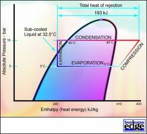
FIGURE 9
NEXT VOL 4:
More on the Vapour Compression Cycle and an introduction to the Absorption Cycle.
