 Cassette Split Systems
 Safety Gloves
 UV Leak Detection
 Condensate Drain Pipe
 Nitrogen Regulators
 Filter Driers
 Filter Cores for Core Shells
Vol 19 – Liquid Line Receivers
Author Mike Creamer, Business Edge Ltd
AIR CONDITIONING TECHNOLOGY
Volume 19
LIQUID REFRIGERANT RECEIVERS
Volume 19 of the series covers Liquid Refrigerant Receivers and concludes our study of the major refrigeration components.
FUNCTION
Refrigerant receivers are only installed in a refrigerant system when absolutely necessary in order to maintain simplicity and avoid excess cost. Receivers require a minimum operating refrigerant charge which adds to the overall system charge, cost and increased losses in the event of a major leak. The Liquid Refrigerant Receiver, situated on the discharge side of the condenser to “receive” refrigerant as a sub-cooled liquid, is normally fitted for the following reasons:
- On larger systems it will be necessary to temporarily store the total system refrigerant charge or a portion of the refrigerant charge whilst carrying out service or repairs on part or the whole of the system. In some water-cooled condenser systems, the condenser also serves as a receiver, provided the total refrigerant charge does not exceed its storage capacity, in which case a separate receiver will be installed.
The receiver must be selected to hold the full system refrigerant charge when only 80 % full to avoid risk of explosion when an increase of refrigerant temperature occurs. The 20 % free volume will allow the refrigerant liquid to expand into the gaseous region without problem.
The receiver acts as a storage point from where the refrigerant is discharged to the thermostatic expansion valve(s). To ensure that only liquid is discharged, the receiver will have a dip-tube fitted to pick-up liquid refrigerant from the bottom of the vessel. Any gas will build up at the top of the vessel and is prevented from exiting the receiver by a sealing charge” dependent on diameter of the vessel and connection size. A typical receiver configuration is shown in Figure 1.
2. On systems utilising multiple evaporators, where the liquid refrigerant normally present in an evaporator is not required at low load or off stage conditions, a receiver is require allowing the unused refrigerant to be held elsewhere other than the condenser.
3. On systems requiring pump down operation, where the refrigerant in one or more evaporators is completely evacuated when the load is satisfied, a receiver is used to hold the excess refrigerant charge. The receiver will be designed to hold the entirety of the operative charge plus a percentage determined at the selection stage. This is covered in the relevant section below.
4. The receiver provides a housing for the systems over pressure protective and safety devices. These can take the form of:
- Fusible plug.
- Bursting disc.
- Safety relief valve.
- The type of safety device fitted depends on the capacity of the system.
5. Receivers accommodate the excess refrigerant due to fluctuating charge in the low and high pressure sides of a system and allow the condenser to be virtually free of liquid thus maximising the effective condensing surface and overall efficiency of the condenser and the system as a whole. Liquid refrigerant in the receiver normally experiences further sub-cooling with attendant benefits to system efficiency.
6. On systems using air-cooled condensers, receivers provide sufficient refrigerant to ensure the liquid line(s) are completely full of liquid refrigerant on start-up to avoid starvation of the TEV and evaporator which would otherwise lead to cycling / shutdown through tripping of the low pressure cut out.
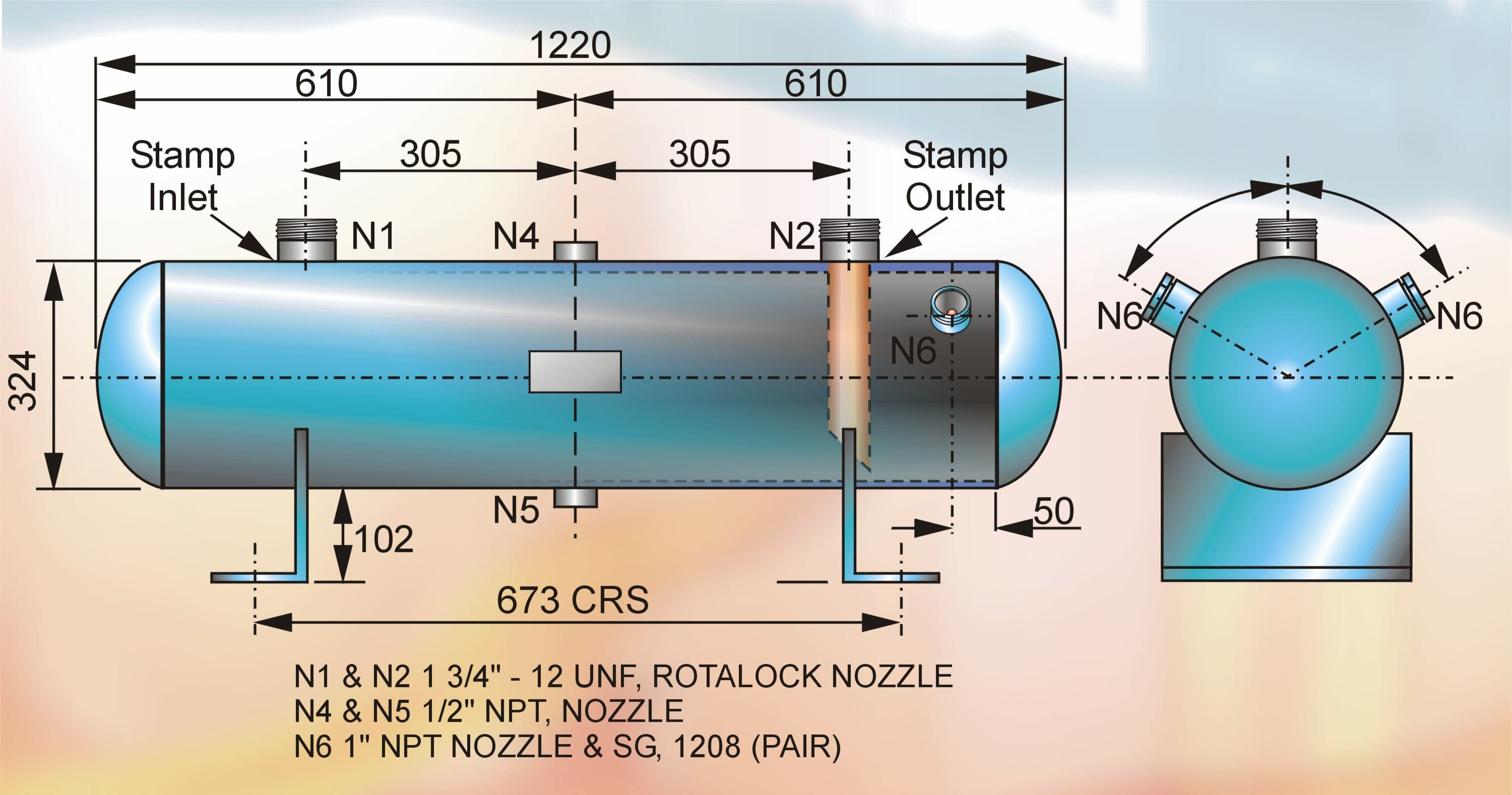
FIGURE 1
POSITIONING
The Liquid Receiver should be positioned as closely as possible to the condenser with the interconnecting pipework arranged to allow free drainage from condenser to the receiver. The pipework must not cause excessive friction pressure loss or gas binding and must have adequately sized valves and fittings.
Positioning of the receiver is also dependent on the type of installation. The installer is usually left to decide on the receiver’s ultimate positioning. Some factors that may influence this decision are:
- Size of compressor pack.
- Length of discharge line from relief valve.
- Ambient temperatures.
- Increased sub-cooling requirements.
Siting that will allow the receiver to be exposed to direct solar radiation must be avoided. When installed internally, do not site near steam pipework or high temperature plant. Excess heating of the receiver will diminish plant efficiency and would be dangerous if the receiver were too full.
If the receiver is installed outdoors and the plant is required to operate in winter, it may be necessary to install trace heaters to maintain adequate pressure in the receiver in order to avoid system problems at start up.
SECURING/MOUNTING
There are two basic mounting options for receivers:
- Stud mounting. A stud is provided to enable the installation team to secure the receiver to a plinth. This method is predominantly used when the receiver is part of a multiple compressor pack.
- Leg/bracket mounting. This provides for the most stable mounting and is used for stand-alone receivers for large installations.
Compressor mounting plates can also be fitted on request.
MAINTENANCE
A Liquid Receiver is a pressure vessel and must be treated with care and in accordance with current regulations and directives. Support the receiver clear of the floor to avoid contact with ground surface water which will lead to corrosion and ensure it is level. The receiver should also be protected from corrosive atmosphere and shielded against physical damage, particularly from heavy vehicles and falling objects.
Routine inspection, periodic cleaning and painting is strongly recommended.
CAPACITY RANGE
The receiver is rated on its capacity to hold the “pump-down” charge (kg). Receivers from manufacturers can range from 1.6kg to 1000kg pump-down based on standard catalogue figures at a temperature of 40 Deg C (104 Deg F) for HCFC22.
In addition to the standard capacity receivers, O.E.M models are available to hold any charge.
CONSTRUCTION
Basically, the receiver is a holding tank and, as such, is fairly simple in construction. There are four types of part in the assembly.
- The shell, made from seamless steel tube.
- The end caps, made for drawn steel plate.
iii. The connection bosses, made from steel billet.
- The dip tube and nozzles, made from ERW or seamless drawn tube.
Assembly of these parts is achieved by welding to exacting standards by suitably qualified personnel. Design, manufacture and assembly of receivers must conform to the various pressure vessel rules and regulations governing the country in which they are to be used.
There are generally only two types of liquid receiver (horizontal and vertical). The vertical receiver is more common on compressor packs in order to reduce the footprint of the equipment, particularly where floor space is restricted.
DESIGN
The first step of the design function is to establish the type of receiver required. i.e. Vertical or Horizontal.
The receiver must then be sized for the pump down capacity including the safety margin allowance. The maximum operating charge must be determined for the system plus a percentage for long runs of suction, liquid and discharge pipework. It is essential that the maximum operating charge be determined taking into consideration, for example, the winter charge in an air cooled condenser having flooded head pressure control, this being much greater than normal summer charge.
The storage capacity of the receiver is then based on the liquid occupying no more than 90% of the internal volume when the temperature of the refrigerant is 40 Deg. C. The final capacity of the receiver should always be greater than the sum of the maximum operating charge plus the sealing charge, which is dependent on vessel diameter and connection size.
The sealing charge prevents gaseous refrigerant from escaping downstream by ensuring that when the system is fully utilising the design refrigerant charge, there is still a small amount left at the base of the receiver to ensure only liquid leaves the receiver thus providing the expansion device with liquid only. Table 1 defines the sealing charge as a percentage of pump down capacity:
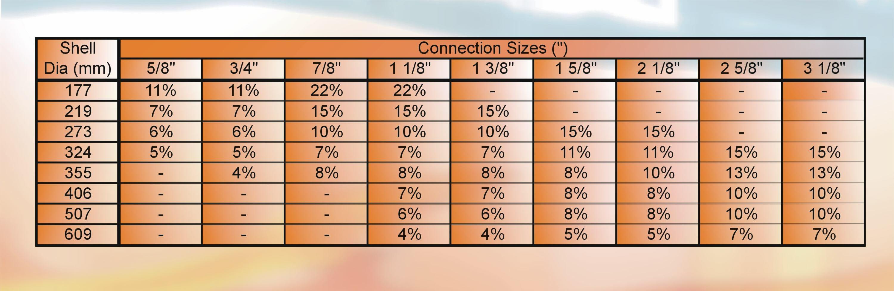
TABLE 1
Summary
max. system charge
Capacity(kg) = ———————— + sealing charge
0.9
The resultant capacity must then be converted to an internal volume for the refrigerant to be used. At the maximum operating temperature/pressure, a given amount of the liquid refrigerant will occupy a specific volume (m3/kg), obtainable from the Pressure/Enthalpy chart or tables of refrigerant thermo-physical properties for the relevant refrigerant. Density (kg/m3) can also be used in these calculations.
DESIGN CODE
The next important step is to establish the design code to be used. Vessels are designed in accordance with the category they fall into. Vessels are classified by pressure multiplied by volume, P x V. A typical example of classification by the product of pressure and volume is shown in fig. 2.
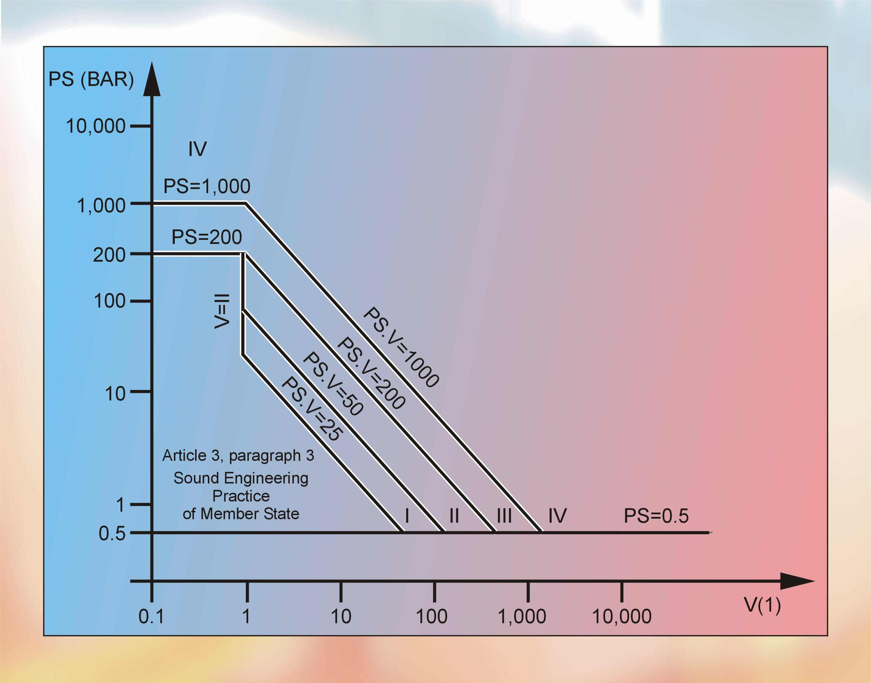
FIGURE 2
RECEIVER ANCILLARY EQUIPMENT
Typical equipment installed as part of the receiver package can include:
1: Pressure relief devices.
2: Inlet and outlet valves.
3: Sight-glass.
4: Liquid level column.
5: Dial level indicator.
6: Liquid level switch (electronic output).
7: Cool gas connection.
8: Heat exchangers.
In order to ensure unrestricted flow from the condenser to the receiver, the pressure in the receiver must be lower than that at the condenser outlet. Alternatively, the elevation of the condenser above the receiver must allow a refrigerant column high enough to overcome the pressure difference. In addition, the refrigerant piping diameter from the condenser to the receiver must be of adequate diameter to ensure minimal friction loss.
The receiver and the pipe work leading to it must provide a free flow of liquid from the condenser to the receiver by equalising the pressures between each so that the receiver is not able to build up a higher pressure than the condenser. This can be achieved by ensuring that the condenser drain line is sized and arranged to allow liquid to flow out of the condenser whilst allowing gas from the receiver to pass in the opposite direction to the condenser. The drain line should be sized to achieve no more than 0.5 – 0.75 m/s liquid velocity. Piping should have adequate downhill slope without liquid traps.
Alternatively, the drain line between the condenser and receiver can be fitted with a separate vent line to permit receiver and condenser pressures to equalise, although the discharge gas from the compressor must be prevented from entering the vent line by fitting a non-return valve in the vent line.
NEXT MONTH: Volume 20 – Pressure Relief & Safety Devices used in the Vapour Compression Refrigeration Cycle
DISCLAIMER: Whilst every effort is made to ensure absolute accuracy, Business Edge Ltd will not accept any responsibility or liability for direct or indirect losses arising from the use of the data contained in this series of articles.
