

In last month’s article we concluded the first of a series of articles covering Humidification. In this months journal we begin the second series of articles looking at Humidification Applications.
Load Estimation
The following series of articles within the Application Section will identify the parameters required to calculate a humidification load for a given space, relative to a comfort-conditioned building or spaces within a building. The result will be used to select and apply different types of humidification systems to obtain the required space condition.
There are two types of application, Ducted and Open Space:
Ducted systems incorporate a fan or fans to create a circulation of conditioned air around the building or space. This circulation would include air ductwork or plenums that deliver or extract air, via diffusers, to and from the conditioned space. In other words a positive air circulation system.
Open Space systems are not mechanical as such but rely on natural ventilation to create an air path that can be described as supply and exhaust. These can also be described as total loss systems because no means of re-circulation is incorporated.
In both these applications we need to substantiate the quantity of air that is to be humidified and the psychrometric process points for the start and finish, or on and off moisture level.
Ducted Systems
Firstly let us deal with the Air Quantity for Ducted systems. The purpose to which the space is used will dictate the amount of air that is needed to be circulated and will be dependent on the cooling and heating load. Added to this re-circulated air will be an amount of Outdoor Air. The quantity will also revolve around the number of people occupying the space. The Charted Institute Of Building Service Engineers or The American Society Of Heating, Refrigerating and Air-Conditioning Engineers give recommendations as to how much Outdoor Air is used per person.
Fresh Air is often used to describe Outdoor Air. This is misleading. For comfort applications there would normally be a dust filter and some heating or cooling, there would not be any means of extracting the chemical contaminants such as carbon monoxide given off by our vehicles. Town applications would have a very high concentration of these man made contaminants. For the purposes of this article we will refer to Outdoor Air as air that’s breathed normally.
The Outdoor Air will have a diluting effect on the total supply air quantity, in as much as the concentration of contaminants. The total air supply quantity will be dictated by the heating or cooling requirement within the building. This can be demonstrated by the heat load equation:
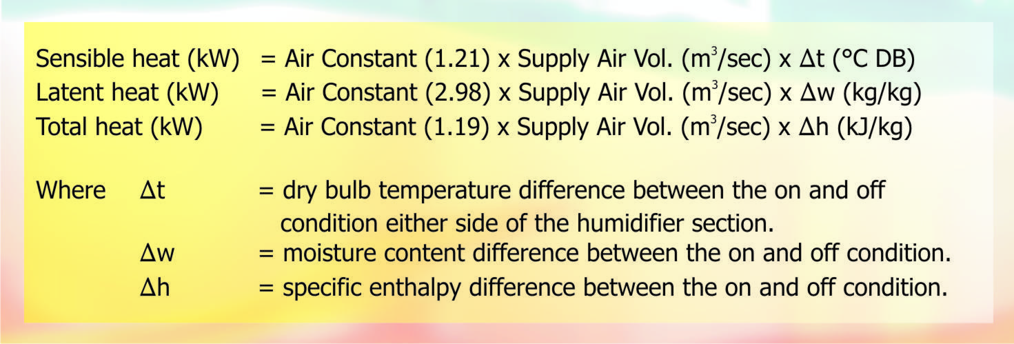
Fig. 1 – Heat Loads
To calculate the humidity load we can take the Outdoor Air quantity as our prime target. The Outdoor Air is mixed with Return Air resulting in a mixed condition entering the humidifier section; the amount of moisture to be added will be of similar magnitude in both cases. By taking the Outdoor Air quantity it saves having to calculate the mixed air condition. A constant volume air system will have a single value to calculate, where as a variable volume air system will have two, maximum and minimum, both of which are made easier by looking at just the Outdoor Air quantity. The system may also have enthalpy control to give maximum benefit of the Outdoor Air condition to control the internal temperature. Again we need to look at the maximum and minimum values.
When calculating absorption distances we must remember to use the mixed air condition as our starting point rather than the Outdoor Air temperature.
Open Space
Open Space applications are not scientific in approach. We still need to establish an air quantity but we must also calculate the ventilation losses that will occur in the building or space. This is based on an assessment of the buildings’ ability to be airtight. The tightness of a building is not just a function of the fabric; we also need to take account of the building use. Warehouse operations tend to have large doors that allow machinery or transportation of product in and out. A printing works, for example, would be moving rolls or pallets of paper in then moving pallets of finished print out. The doors could be open for a large portion of the day. A carding mill would again have large bales of wool coming in and large bins of wool going out, both of which will require mechanical handling, so fork lift truck will be evident along with large doors.
The number of air changes that take place in one hour need to be assessed and these will be dependant on the building fabric and the building use. This is normally expressed as a value of one, two or three air changes per hour. Very tight buildings could be as low as half an air change per hour and the design and quantity of the ventilation would again be a function of the number of people.
Take the internal floor area and multiply by the occupied height, normally 2.5 to 3 metres. This establishes the cubic area of the building or space, multiply it by the number of air changes per hour, this gives us an air volume. One way of looking at the problem is to think of the space as a large mixing box in a ducted system, that has a majority re-circulated component plus an amount of outdoor air naturally ingressing into the space, equivalent to the amount of indoor, or conditioned air, escaping to the outside.
Psychrometric Process
There needs to be a start and stop point to allow us to quantify the amount of moisture to be added. Our example has Outdoor Air, in the winter at 5oC DB / Saturated or 100% RH. The air would be heated to say 22oC DB, 33% RH. Values for each point are tabulated below.
| Start | Finish | |
| Dry Bulb | 22oC | 22oC |
| Wet Bulb | 13oC | 15.7oC |
| Dew Point | 5oC | 11.5oC |
| Relative Humidity | 33% | 50% |
| Moisture Content | .0035kg/kg | .0085kg/kg |
| Specific Volume | .844m3/kg | .847m3/kg |
The formula for calculating the humidity load is:
Load (kg/hr) = Air Volume (m3/sec) x Moisture Difference (kg/kg) x 3600 sec.
Specific Volume (m3/kg)
Air Volume
Let us assume that the ventilation rate or supply air volume for this calculation is 3.2m3/sec.
Moisture Difference
Heating the Outdoor Air from 5 to 22oC DB is a sensible heating process where moisture is not added or taken away, therefore the moisture content remains the same at .0035kg/kg. Moisture is then added to take the Relative Humidity from 33% to 50%, equivalent to a moisture content of .0085kg/kg. An isothermal process would follow the dry bulb line on the psychrometric chart vertically, not adding sensible heat to the air but latent. An adiabatic process would follow the wet bulb line upward, demonstrating a cooling effect on the air, which would be a negative sensible and latent process. Whichever system is used to introduce the moisture the humidity load is the same.
Therefore moisture content difference is .00650 – .00379 = .00271kg/kg
Time
The 3600 seconds will convert the answer to hours. If you used the air volume units of m3/hr we would not use this conversion factor and still have a result in kg/hr. The preferred unit of stating air volume in the UK is m3/sec.
Specific Volume
As we have two process points, the start and finish, when moisture is added the Specific Volume will increase. This is now a moving target and difficult to combine into the equation. The answer is to take the mean of the two values.
.844 + .874 = .859m3/kg
2
The Calculation
Load (kg/hr) = Air Volume (3.2m3/sec) x Moisture Difference (.0031kg/kg) x 3600 sec.
Specific Volume (.859m3/kg)
Load = 40.23kg/hr
Selection
The air system and heating / cooling loads will dictate which type of humidifier is chosen. The choices are Isothermal, steam, or Adiabatic, cold water. From our previous articles the Isothermal process will not effect the dry bulb temperature where as the Adiabatic will produce a cooling effect on the air supply. This cooling effect may be in keeping with the building requirement. It could be a net cooling building with large internal loads that are present year round. In which case this cooling phenomena will be beneficial.
On the other hand the criteria may be first cost and the cost of ownership may be dealt with within another budget or indeed another organisation. We will start with the most popular humidifier and apply it to the Ducted and Open space examples in detail.
The most popular, because of its first cost is the open-ended electrode boiler that will generate steam for insertion into the airflow as an Isothermal process. The ranges that are available come in incremental sizes and we should select one that meets the calculated load. Our example requires a 40kg capacity therefore we would select a 45kg/hr unit and down grade its capacity to reflect our calculated duty.
The 45kg Humidifier has a single steam outlet, 54mm in diameter each. It requires a mains water supply, a main drain, a mains electrical supply and a control signal. Firstly we need to position the steam into the air path by using either a single steam pipe or a multiple steam pipe. The absorption distance available to us will dictate which we use.
Absorption distance
This is the distance required from the initial introduction of the steam to the point where the moisture is totally absorbed into the air. This can be seen by the disappearance of the plume, or wisps of steam. A rule of thumb for normal comfort conditions is 1 to 2 metres. But we do need to find out more accurately what this distance is to ensure the length of the air handler is at its optimum or there may be a bend or diffuser in the ductwork very close to the point of steam injection. If an element, downstream of the steam pipe is too close, the plume will foul the component and cause condensation. This will puddle and either remain there and become a health hazard or drip out onto the plant room floor or, even worse, soak the ceiling tile and drop into the occupied space. So it is quite important the absorption distance is known.
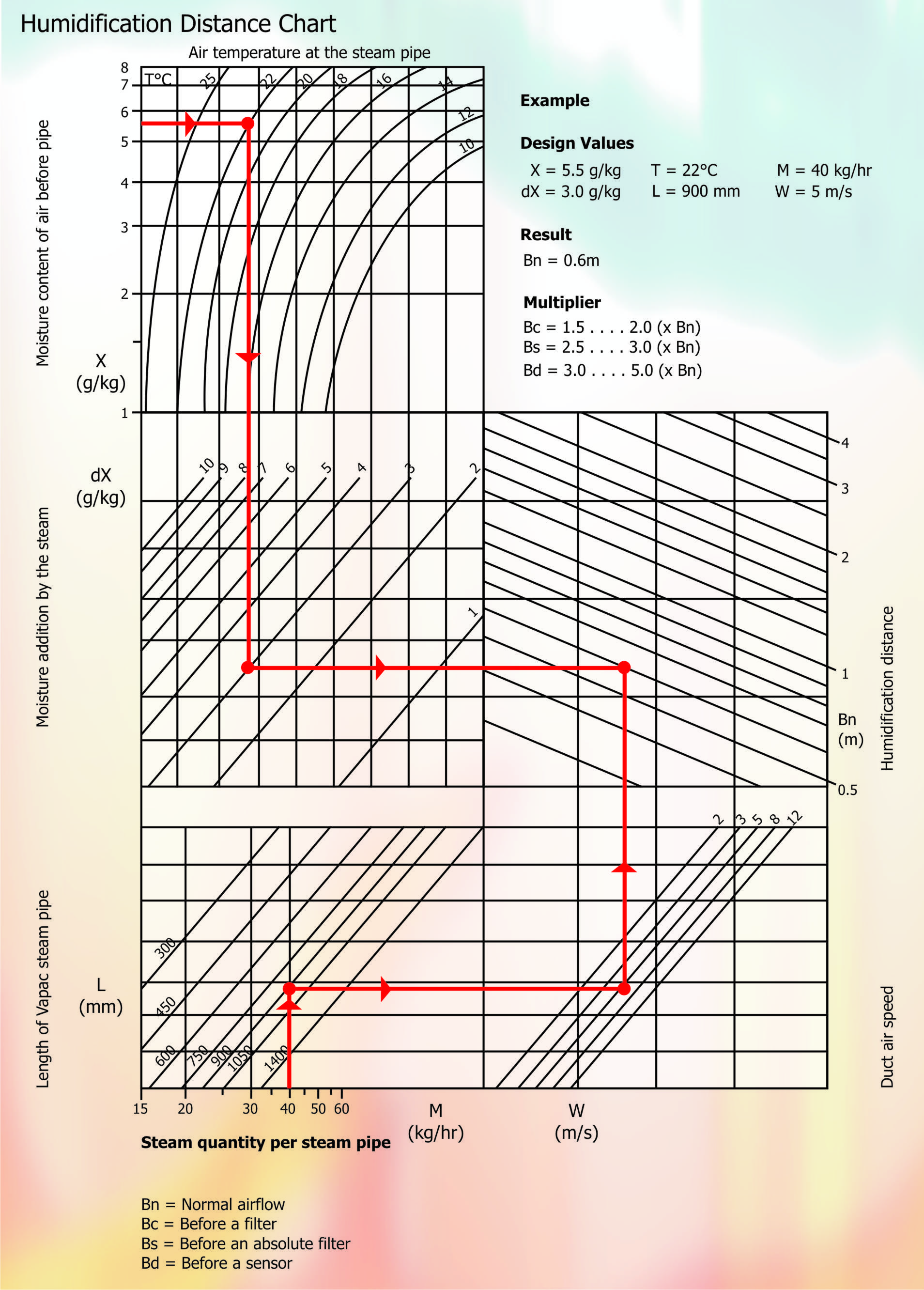
Chart 1 – Humidification Distance Chart
We would use a Humidification Distance Chart. We enter the chart at two points and work towards an intersection. This point gives us a value in metres, which can be multiplied by a further value dependant on the next component after the point of steam injection.
Our example has a moisture content before the steam pipe of .0035kg/kg or 3.5g/kg. Enter the graph at the top left hand side and draw a line across at 3.5g/kg to dissect the 22oC line, which represents the supply air dry bulb temperature at the steam pipe. Draw a line vertically down from this point until you dissect the diagonal line that represents the moisture addition by the steam. Our example is 8.5g/kg – 3.5g/kg = 3g/kg. Draw a horizontal line left to right, stopping at the Bn scale.
We now enter the graph from the bottom scale that indicates the quantity of steam being applied to the pipe. Our example requires 40kg/kg. At this point we do need to know what the cross sectional size of the air-handling unit is or the ductwork. For our example we will assume the internal dimensions to be 800 x 800mm high giving a cross sectional area of .64m2. We will select one 750mm long steam pipe receiving 40kg/hr of steam. The goal is to distribute the steam across as much of the air path as possible hence the longest pipe has been selected to fit into the width of the AHU.
From 40kg/hr scale draw a vertical line to cut the 750mm long steam pipeline. Then draw a horizontal line to cut the calculated air speed line. In our case it would be 3.2m3/sec divided by .64m2 cross sectional area = 5m/sec. From this point draw a vertical line up the scale until we cut the previous line drawn earlier. Read off the value for Bn from the scale, .6m.
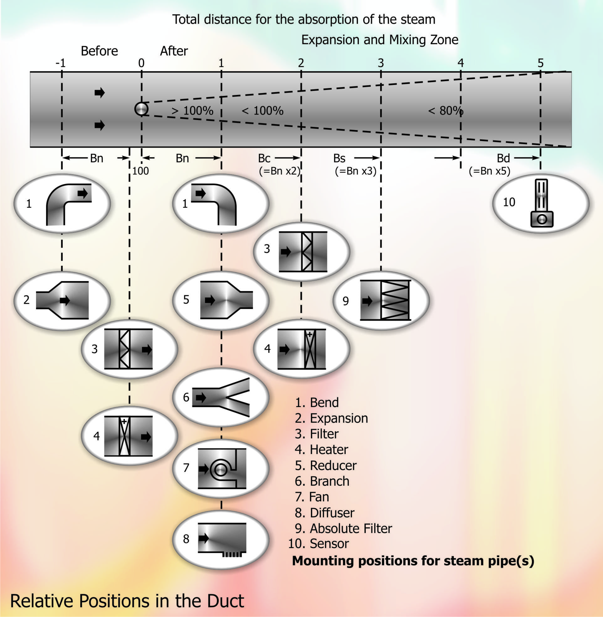
Chart 2 – Relative Positions in the duct
We can now use this value relevant to the next element in the direction of the air. Say it was the supply air fan, which is represented by number 7 in the Relative Position Chart. The absorption distance can be taken as 600mm. If however there was a course filter represented by number 3, the distance must be multiplied by 2. If we had a bag filter immediately after, represented by number 9 the distance must be multiplied by 3.
The high limit humidity sensor represented by number 10 must be positioned 5 times Bn away from the point of injection. This chart becomes extremely useful in positioning the pipes to ensure the steam introduced into the air steam is totally absorbed and not separating out and running to drain.
Positioning the Steam Pipes
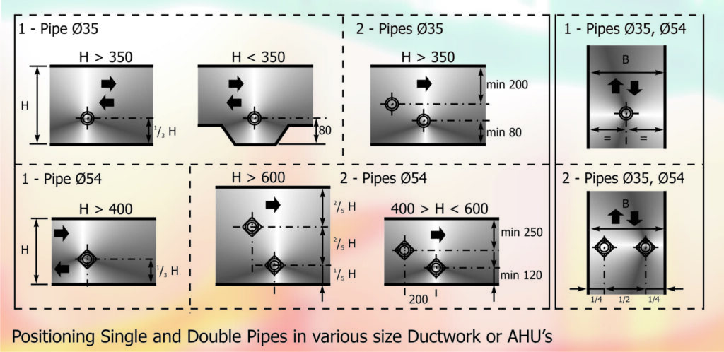
Chart 3 – Positioning single and double pipes
The diagram shows the rules that should be followed when positioning single and double pipes in various size duct work or AHU’s. Covering both horizontal and vertical air paths. The important thing to remember is the holes or nozzles in an atmospheric steam pipe should be positioned at 90o to the airflow, whether it is horizontal or vertical.
If the absorption distance is too long for the space available a further solution must be found. The clue was given earlier. We need to increase the steam insertion points across the air path. The cheapest method uses two similar steam pipes rather than the one. We can safely extrapolate from the chart, choosing the 750mm-steam pipe but only passing 20kg/hr of steam into each. Again moving horizontally to dissect the 5.2m/sec velocity line and moving vertically to cut our previous moisture addition line at 340mm. Significantly the absorption distance has not been halved by doubling the number of pipes, so it is important that the selection is carried out each time to get a correct answer.
The extrapolation used above should not be extended to three, four or five pipes, as the answers would not be accurate enough to fulfil our prediction criteria. It is also important that when splitting a steam line between two pipes the distance from the header to each pipe is equidistant and contains the same number of bends. This keeps the pressure drops equal therefore delivering an equal amount of steam out of each pipe.
If the distance is still to long for the available space a multiple nozzle arrangement is the only answer. This is normally performed with a computer selection programme but the essence of the calculation is to distribute steam outlets across the full cross sectional face of the air stream. This would involve a top and bottom steam header interconnected with multiples of smaller steam pipes. Each pipe having multiple holes or nozzles along it’s length allowing steam to be distributed in all directions. As a rough guide each nozzle has a maximum steam capacity of ½ kg/hr (.5kg/hr). The secret is to obtain the best aspect ratio, nozzles to area to ensure the total; capacity of steam can be distributed across the full face of the air path.
This appliance can reduce the absorption distance to as little as 100mm. Why bother you may ask, well if it is not necessary then exactly, why bother, stay with the cost-effective solution. But if the plant room is very tight and the alternative of extending the plant room wall is not available then a multipipe is the only solution.
Open Space
Selection of the steam humidifier would be similar to the above. However, as we do not have ductwork to distribute the air and moisture into the space, a room distribution unit is necessary. This is a steam manifold mounted in a box with a fan blowing air across the nozzles. Not a particularly elegant piece of equipment but functional. The air volume and speed is set to an optimum level to prevent spitting at high speeds but still ensuring steam distribution takes place at low speeds.
We would select a number of units to ensure even distribution of moisture takes place across the conditioned space. It may require two or more units, in which case you would select the number of matching humidifiers and room distribution units (RDU`s) to suit the application. Care should be taken if two RDU’s are connected to one humidifier that the steam distribution pipe work incorporates a manifold rather than a ‘T’ piece and that each leg is of equal distance and equal number of bends. The two units should also be mounted at the same height. Further information is given in the pipe work section of this article.
Steam Distribution
We need to transport the steam, atmospheric pressure from the generator or boiler to the steam pipes. Try to keep the pipe work straight and as short as possible at all times. Creating a trap by going around a roof beam, for example, in a vertical U shape will form a very effective steam trap. This will fill with water and prevent steam passing through to the distribution point. If it is unavoidable use a condensate separator at the lowest point to collect the condensed steam and run it to a drain.
The pipe work can be run in copper or stainless steel especially if long or torturous routes are planned. It is important that insulation is used to cover this pipe to reduce temperature loss therefore incurring condensation inside which ultimately cost money. Use a high temperature rated insulation, as the pipe work will be operating at 100oC
The most common transmission media is a flexible hose that just slips over the end of the appliance and held on with a jubilee clip. This is by far the easiest and cheapest method if the runs are short and straightforward. The hose can be braided or unbranded, but both types will have a maximum bend radius that can be achieved before it kinks. A 35mm hose would have a minimum radius of 250mm and a 54mm hose would have a 500mm radius. So care must be taken to prevent tight bends. When operating at 100oC hoses become more pliable and kink easier.
Steam Pipes
We discussed the steam pipe previously with regard to how many and their relative position within the air stream. There are two types available and referred to as positive and negative slope pipes. The positive slope will be angled up when the flange is mounted to a horizontal duct wall, so that any condensate that does form will drain back down in the direction of the steam. This water will then either run to waste via a separator or back into the steam generator bottle. The negative slope pipe will be angled the opposite way so any Condensate will run to the far end of the pipe. There will be a drain connection and line to take the water away to waste. There is standard steam pipe design; it tends to be the choice of the specific manufacturer.
NOTE: Our sincere thanks go to Mike Creamer of Business Edge Ltd. Re-creation of Drawings by Business Edge Ltd.
DISCLAIMER: Whilst every effort is made to ensure absolute accuracy, Business Edge Ltd. will not accept any responsibility or liability for direct or indirect losses arising from the use of the data contained in this series of articles.